


Setup
311511G 19
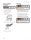
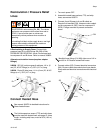
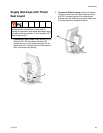
Recirculation / Pressure Relief
Lines
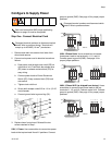
If Recirculating to Supply Drum: Connect high
pressure hose (R) to relief fittings (BA, BB) of both
PRESSURE RELIEF/SPRAY valves. Route hose back
to component A and B drums. Refer to manual 309852.
Alternate recirculation hoses (requires adapter
fittings):
249508 - ISO (A) (moisture guard) red hose, 1/4 in. (6
mm) ID; #5 JIC fittings (m x f); 35 ft (10.7 m) long.
249509 - Resin (B) blue hose; 1/4 in. (6 mm) ID, #6 JIC
fittings (m x f), 35 ft (10.7 m) long.
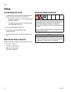
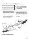
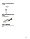
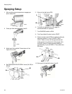
Connect Heated Hose
1. Turn main power OFF.
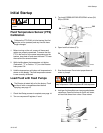
2. Assemble heated hose sections, FTS, and whip
hose; see manual 309572.
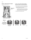
3. Connect A and B hoses to A and B outlets on
Reactor fluid manifold (FM). Hoses are color coded:
red for component A (ISO), blue for component B
(RES). Fittings are sized to prevent connection
errors.
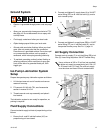
4. Connect cables (SS). Connect electrical connectors
(NN). Be sure cables have slack when hose bends.
Wrap cable and electrical connections with electrical
tape.
Do not install shutoffs downstream of the PRESSURE
RELIEF/SPRAY valve outlets (BA, BB). The valves
function as over pressure relief valves when set to
SPRAY. Lines must be open so valves can
automatically relieve pressure when machine is
operating.
If circulating fluid back to the supply drums, use high
pressure hose rated to withstand the maximum
working pressure of this equipment.
See manual 309572 for detailed instructions for
Graco heated hoses.
The fluid temperature sensor (FTS) and whip hose
must be used with heated hose; see page 19. Hose
length, including whip hose, must be 60 ft (18.3 m)
minimum.
BB
BA
ti8441a
R
R
Manifold hose fittings (VV, WW) allow use of 1/4 in.
and 3/8 in. ID Reactor heated fluid hoses.
FM
VV
WW
ti8444a
ti8444a
SS
NN