


Setup
311511G 15
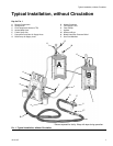
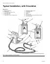
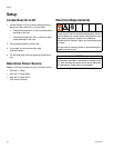
Configure to Supply Power
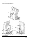
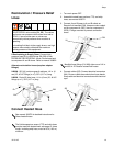
Step One - Connect Electrical Cord
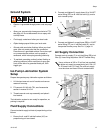
1. Remove and retain two screws from lower front
shroud and remove.
2. Connect main power cord to electrical console as
follows:
a. Feed power cord through strain relief (SR) on
right side of unit. Push black die release lever
(RL) down to release contacts block (PD) for
easy wiring.
b. Connect power leads to Power Disconnect
Switch (PD). Snap contacts block (PD) back
onto switch.
c. Tighten strain relief nut.
d. Strain relief accepts cords 0.59 to 1.0 in. (15-25
mm) diameter.
e. Connect ground wire to ground lug (GL).
3. Replace lower front shroud. Reinstall the two
screws retained in Step 1.
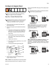
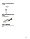
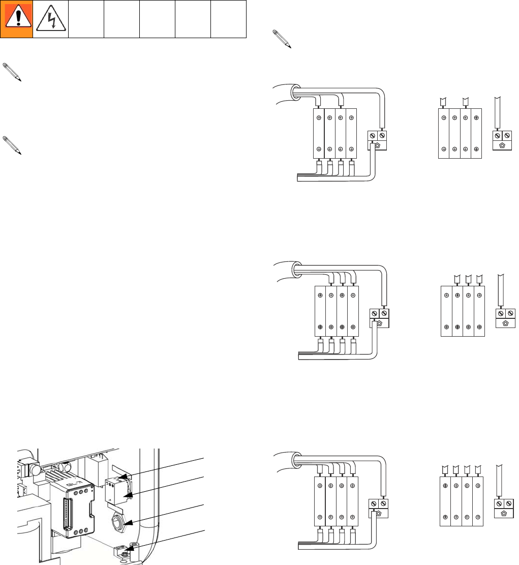
230V, 1 Phase: Use a screwdriver to connect two power
leads to the top terminals N and L2 positions. Connect
green to ground (GND). See page 16 for proper jumper
positions.
230V, 3 Phase Delta: Use a screwdriver to connect
three power leads to top terminals L1, L2, and L3.
Connect green to ground (GND). See page 16 for
proper jumper positions.
380V, 3 Phase WYE (as shipped from factory): Use a
screwdriver to connect three power leads to the top
terminals L1, L2, and L3. Connect neutral to N. Connect
green to ground (GND). See page 16 for proper jumper
positions.
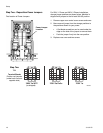
Both cord connection AND jumper positioning
steps on page 16 must be completed.
Disregard terminal numbers on disconnect switch
blocks. Wire to positions shown. Terminals will
accept up to #8 AWG (10 mm
2
) conductors.
SR
PD
ti8608a
GL
RL
Disregard terminal numbers on disconnect switch
blocks. Wire to positions shown.
,
,
,
,
0%
'2.$
, , ,.
.
ti8611a
,
,
,
,
0%
'2.$
, , ,.
.
ti8612a
,
,
.
,.
,
,
0%
'2.$
, , ,
.
ti8613a