


8
Level
Installation, operation & maintenance instructions
IP152, Rev A
D
April 2012
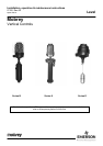
Series D
Installation Instructions
Installation shall be carried out by suitably trained personnel in accordance with applicable codes of practice.
1. Remove all sealing tapes, tie strings and protective packings from
the control prior to installation. If float rod length needs adjusting to
allow a higher operating level, refer to adjustment notes on page 8.
Note: Careful handling is required at all times to ensure float and float
rod are not damaged or bent.
If a control is fitted with a longer than standard rod (i.e. dimension H is
greater than that shown in the adjoining table) or the liquid is subject to
excessive turbulence or agitation, then a stilling tube should be fitted.
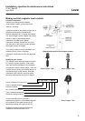
2. If control has been ordered without a mounting flange, the float unit
must be removed from the control before the switch head can be
mounted on the vessel via the 1”NPT threaded boss provided. This is
achieved by locating the Stop Assembly at the base of the 1”NPT
threaded boss and easing the spring clip, allowing the entire float
assembly to be removed.
3. Mount the switch head on the vessel using the flange (if provided) or
the 1”NPT threaded boss ensuring that the centre line axis is vertical to
the eye. If the threaded boss is used, ensure a pressure tight seal is
formed between it and the vessel. Use only the hexagonal boss to
tighten the 1”NPT thread into the mounting boss or flange. Torque
flange bolts in accordance with torques shown on page 12.
4. Ensure that magnet is free from swarf and debris before re-fitting to
switch head. Locate the two ends of the spring clip in the two cross
holes in the base of the pressure tube ensuring that float assembly is
free to move vertically and is securely retained by the Stop Assembly.
5. Remove switch head cover to reveal terminal block(s) to which
electrical connections are to be made:-
Flameproof models: Locate and slacken off M5 socket head safety
grub screw on side of cover adjacent to base joint. Place a bar across
the top of the cover, locating in the castellations. The cover can now be
unscrewed from the base using the bar as a lever.
Weatherproof models: The cover can be removed by unscrewing the
single hexagon nut at the crown of the cover.
6. Connect electrical wiring via the conduit entries using a suitable
cable gland. Note that the base of the enclosure is rotatable on the
pressure tube to allow the most convenient orientation of the conduit
entry.
Refer to wiring notes on page 4.
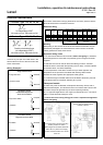
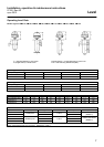
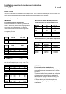
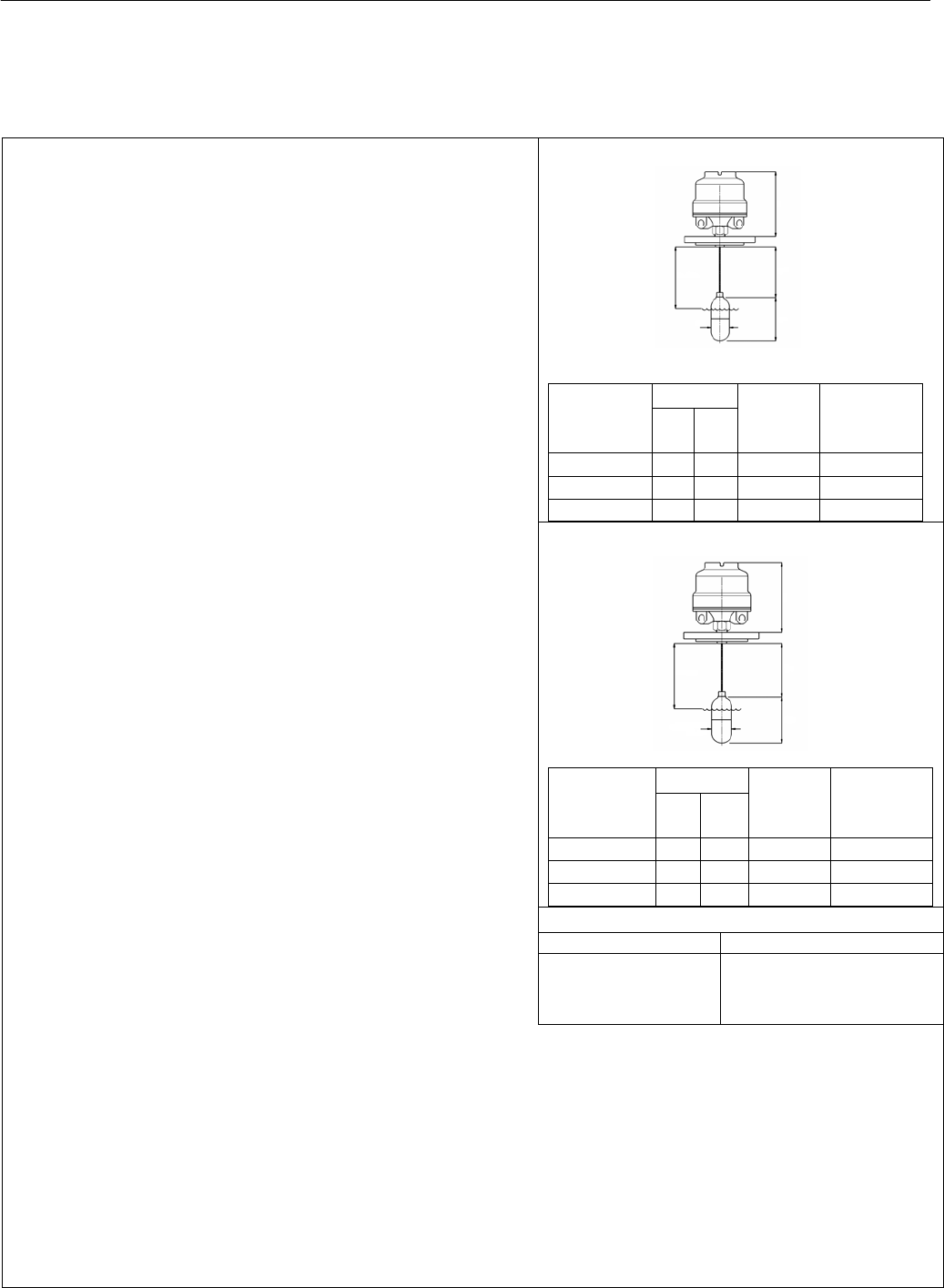
*Float rod may be shortened to suit
H dimension
w
hen used
with :
11F Switch
adjustment
Wet switching
differential
Min
H
Max
H
R4N R7A R71 155 315 none 20mm
S4N S7A S71 155 315 94mm 114mm max.
L4N
*F
loat rod may be shortened to suit
H dimension
w
hen used
with :
12F,13F,14F Switch
adjustment
Wet switching
differential
Min
H
Max
H
R4N R7A R71 155 415 none 20mm
S4N S7A S71 155 415 94mm 114mm max.
L4N 155 415 194mm 214mm max.
Operating Levels
Lowest operating levels H + 35
Highest operating levels
: see adjustment notes
(H + 35) – (B + 20) where B is
the max. switch adjustment
from table on page 8.
On models with flameproof enclosures type ★7★ the switch mechanism may be raised on the pressure tube to ease access to
the Terminal Block. Ensure that the switch mechanism is re-positioned to its lowest position (i.e. sitting on the limit tube around
the pressure tube) after wiring.
7. Switch point adjustment may now be made if necessary. See page 8.
8. The lugs of the tab washer directly underneath the base must now be bent over to locate on the most appropriate flats of the
hexagon union. This prevents further rotation of the switch head, and is particularly important as it will prevent rotation when
the cover is removed or re-fitted.
9. Check the cover seals are present and in good condition, and then replace the cover.
(i) Before energizing flameproof / Type ★7★ models, ensure the cover locking safety grub screw is replaced and
tightened. Do not energize if the cover locking safety grub screw is missing.
(ii) Before energizing weatherproof / Type ★4★ models, ensure the weatherproofing fibre sealing washer at the crown nut
is in place.
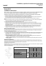
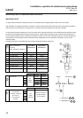
Floats for 3” NB mounting : 11F
Floats for 4” BB mounting : 12F, 13F, 14F
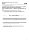
H + 35
G
H*
150
Ø67
H + 35
G
H*
160
Ø88
Ø90
3F . 4F
2F