


4
Level
Installation, operation & maintenance instructions
IP152, Rev A
D
April 2012
Electrical characteristics
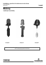
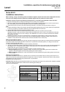
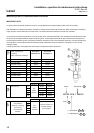
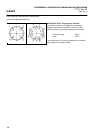
4 Contact Type : D4, X4, P4, H4
2x independent SPST
AA make on rise : BB make on fall
8 Contact Type : D8, X8, P8, H8
Double pole double throw
(4x independent SPST)
AA make on rise : BB make on fall
Note: For DPDT operation, installer must
common any one pair of A and B wires in the
terminal block for each of the two ends of the
switch mechanism.
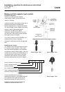
Wiring Examples
Each switch mechanism has flying leads which are factory wired to ceramic
terminal blocks fixed in the switch enclosure.
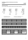
Electrical rating
Type
Temp
wetside
°C
Low
Temp
use
AC max. values AC max. values
VA Volts Amps Watts Volts
Res
amps
Ind
amps
D4, D8 400 Amp. 2000 440 5 50 250 5 0.5
X4, X8 250 Amb. 2000 440 10 50 250 10 0.5
P4, P8 400 Amb. 6 250 0.25 3.6 250 0.25 0.1
H4, H8 250 -100°C 2000 400 5 50 250 5 0.5
Power factor
0.4 mm
Time constant
40ms max.
Warning
Gold plating on the contacts of the P4 and P8 switch mechanisms may be
permanently damaged if the mechanisms are used to switch circuits with
values greater than those shown above.
Important wiring notes
1. To minimize the electrical shock hazard, before energizing it is essential
that the equipment is connected to a protective ground using the terminals
supplied.
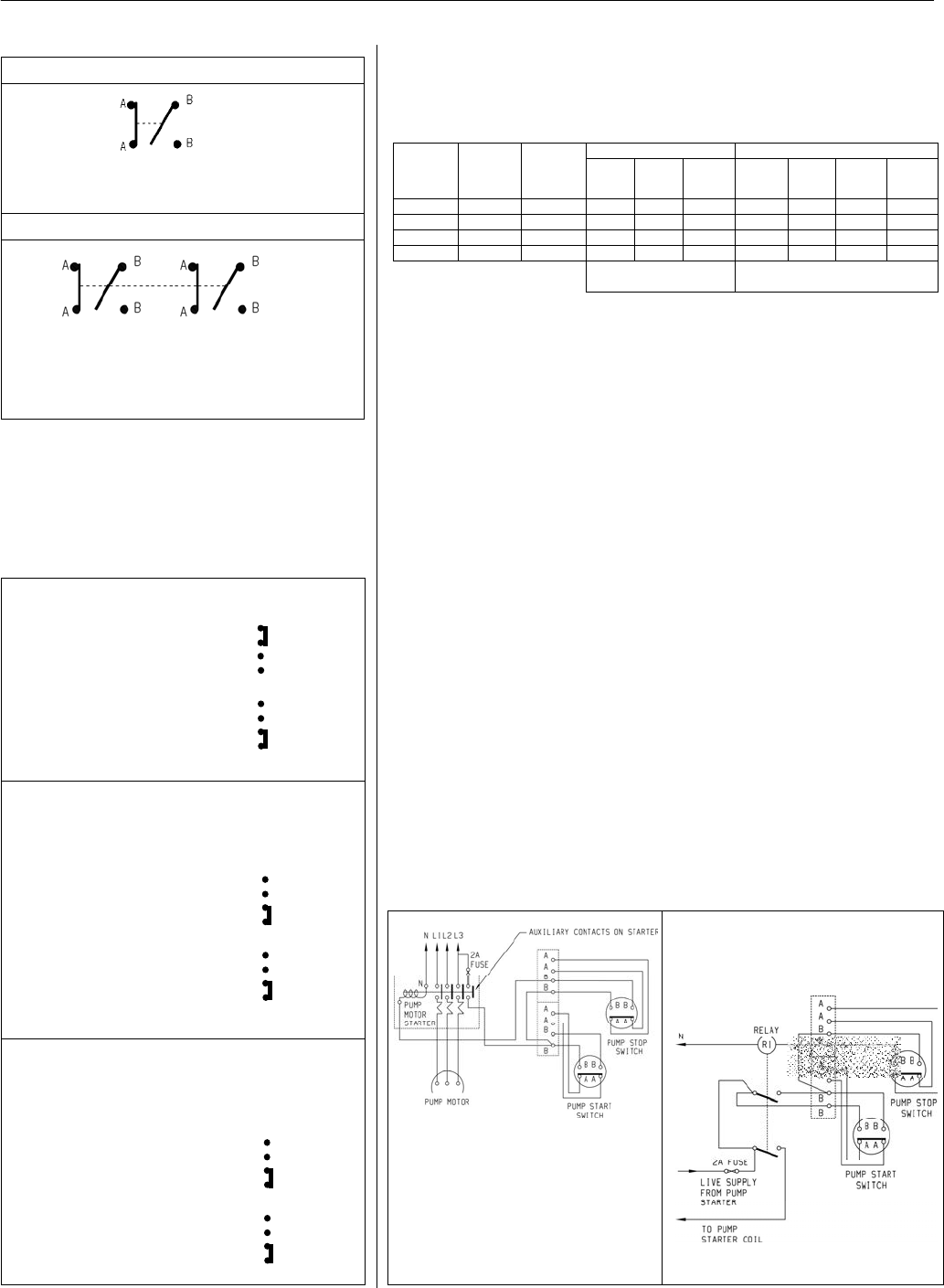
2. Switches must not be used for the direct starting of motors. Contacts
should be wired in series with the operating coils of relays, contactor starters
or solenoid valves, and fused separately.
3. The temperature of the switch enclosure may at times approach the
temperature of the process and suitable heat resisting cables should
therefore be used, together with appropriate cable glands.
4. A sufficient length of flexible cable should be fitted to allow easy removal
of the switch head and displacer assembly at any time.
Flameproof models
5
. Cable entry must be fitted with a flameproof cable entry device, with or
without thread adaptor, and should be used in accordance with a local Code
of Practice subject to agreement by the local Inspecting Authority.
6. U.L. Approved Applications: Use copper conductors 60°/75°C: 140°/167°F
ONLY. Torque terminals to 6kg/cm: 7lb/in.
7. Ensure the cover locking safety grub screw is replaced and tightened
before energizing.
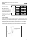
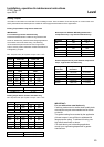
Two switch pump control circuit using
a
uxiliary contacts on starter.
Note diagram shows starter fitted with
250V coil for 3-phase 3-wire supply
connect coil terminal N to line 1 and fit
440V coil.
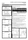
Two switch pump control circuit using
‘
holding’ relay for starters without
auxiliary contacts.
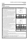
Single-switch Control
Two
-
Switch Control
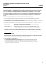
Combined Pump Control
And Low Level Alarm
Two
-
switch Control
High and Low Level Alarm
A
A
B
B
A
A
B
B
A
A
B
B
A
A
B
B
A
A
B
B
A
A
B
B
Alarm ON
Alarm ON
Alarm ON
Alarm ON
Alarm ON
Pump ON
HLA Switch
LLA Switch
Pump Control Switch
LLA Switch
As high level
alarm
As low level alarm