


11
Level
Installation, operation & maintenance instructions
IP152, Rev AD
April
2012
5. Inspect the chamber or stilling tube and remove any deposits.
6. Check float, float rod, and magnet for excessive wear, clean and replace as necessary.
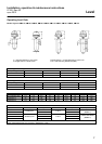
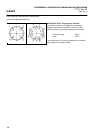
7. Fit replacement joint and reassemble, taking care not to bend the float rod. Use bolt torque values given in tables on page 12.
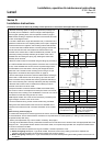
8. Remove the switch head cover and examine the switch mechanism body for any damage. Ensure that the wiring is in good
order and that all screws are tight. Dismantling of switch units is not recommended and replacement of the complete
switch unit will be found to offer the quickest and most economical solution in event of faulty operation.
See page 10.
9. Check sealing gaskets / “O” ring and replace if necessary.
10. Check the cover seals are present and in good condition, and then replace the cover.
(i) Before energizing flameproof / Type ★7★ models, ensure the cover locking safety grub screw is replaced and
tightened. Do not energize if the cover locking safety grub screw is missing.
(ii) Before energizing weatherproof / Type ★4★ models, ensure the weatherproofing fibre sealing washer at the crown nut
is in place.
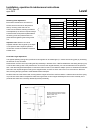
11. If the control is mounted into a chamber, close drain valve connection, open isolating valves and check that the control is
operating at the correct levels.