


INSTALLATION PROCEDURES Eskimo Ice Installation Manual - Remote System
6 L-2448B ENGLISH
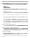
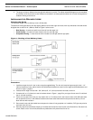
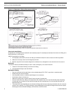
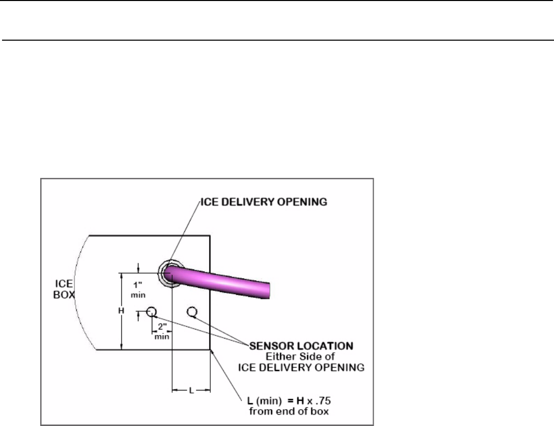
INSTALLING THE ICE-LEVEL SENSOR
To prevent overflow, this sensor stops ice production when the ice in the storage box reaches the level of the sensor. Use
Figure 2 below to determine placement for the ice-level sensor at the storage box location.
1. The sensor must be located below and to the side of the ice-delivery hole. Drill a 23/32" (19mm) hole for sensor.
2. Use the 2 lock nuts provided to secure sensor into the hole.
3. Use marine-grade sealant around the hole if desired. (Remember that the unit may have to be removed at some time.)
4. Route the cable to the auger unit and plug the end into the matching socket.
Figure 2: Location of Ice-Level Sensor (front view)
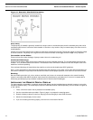
INSTALLING THE REFRIGERANT LINESETS
The linesets, auger, and condensing unit all have quick-connect (QC) fittings. QC fittings allow connection and disconnection of
the system with no loss of refrigerant.
1. Refrigerant lines may run uphill, downhill, or sloping as necessary. They can have bends, but avoid sharp bends that
could kink the tubing.
2. Route the lines directly to each unit, and approach the QC in a straight line.
3. Do not try to screw fittings together that are incorrectly mated, as this will destroy the fittings. Connect the fittings with
this method:
• Lubricate the male fitting face and threads lightly with refrigeration-grade oil.
• Hand-thread the nut of the female QC onto the male-threaded QC by rotating the union nut clockwise.
• Tighten the female thread connection with a wrench while holding the opposite coupling with a wrench. Exception:
If the male QC is held by a metal bracket at each unit, it does not need a wrench on it.
• Tighten each assembly to 35 foot-pounds with a torque wrench. If you don’t have a torque wrench, tighten each
assembly until the fittings “bottom out,” then use a marker to make a line on each coupling half hex. Turn with
wrenches an additional 1/6 to 1/4 turn to completely seal the assembly.
WARNING: If the steps above are not followed and the fittings are cross-threaded together, the fittings will be
destroyed and the warranty voided.
4. Once connections are made, fully insulate the suction line from unit to unit.
INSTALLING THE FEEDWATER SYSTEM
Feedwater for the auger unit should be fresh water supplied by the boat’s potable water system. The water reservoir has a float
switch to ensure the unit does not operate without a water supply.