


Master or Standalone
Gate Setting
27
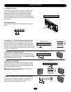
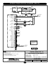
PROGRAM SETTINGS (DIP SWITCH S2)
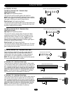
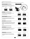
EDGE/PHOTO OPEN
This switch (S2-3) selects edge or photo sensor for the gate
opening protection input.
Open Photo Eye (Pause): When the controller is configured
for photo eyes, the input functions to pause the gate during
the opening cycle. Once the input is cleared the gate
continues to open.
Open Edge: When the controller is configured for safety
edges, the input functions to reverse the gate to the close
limit when the edge is activated during the opening cycle.
EDGE/PHOTO CLOSE
This switch (S2-4) selects edge or photo sensor for the gate
closing protection input.
Close Photo Eye (Reverse): When the controller is
configured for photo eyes, the input functions to reverse the
gate to the open limit when activated during the close cycle.
NOTE: Timer-to-Close will reset if enabled.
Close Edge: When the controller is configured for safety
edges, the input functions to reverse the gate to the open
limit when activated during the close cycle. The entrapment
is not cleared at the limit and the timer to close will be
disabled. The Timer-to-Close may be enabled by activating
the interrupt loop, soft open or hard open input.
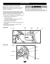
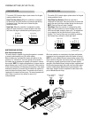
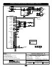
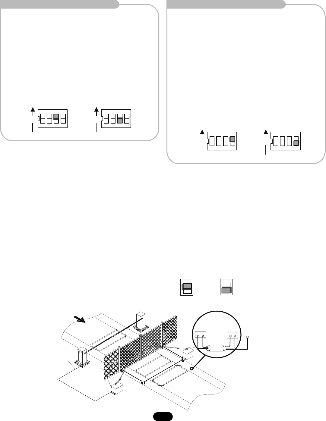
MASTER/SECOND SYSTEMS
Dual Gate Communications
The control board is capable of running the operator in a master
or second mode depending on (S4) switch setting.
Before initiating any command the master unit queries for the
presence of a “second unit” for a time period of one second. If
the master gets no response the operator will operate in a stand
alone mode. NOTE: For single unit applications, a jumper must be
placed between pins 1 and 2 of the J4 connector. In this mode no
further communications will take place during travel. If the master
detects the presence of a second unit the master will continue to
query the second unit during travel. The second unit will send a
response to the master for every query. The second operator will
stop if there is a period of one second or more of no
communications.
ON
CLED PH
OPED PH
1 2 3 4
WARN
MAG
ON
S2
ON
CLED PH
OPED PH
1 2 3 4
WARN
MAG
ON
S2
ON
CLED PH
OPED PH
1 2 3 4
WARN
MAG
ON
S2
ON
CLED PH
OPED PH
1 2 3 4
WARN
MAG
ON
S2
Master
Unit
S4
S4
Second Gate
Setting
Master
Unit
Second
Unit
Second
Unit
ON
ON
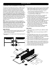
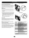
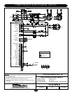
When two operators are connected in dual gate configuration
accessories may be connected to either the master or second.
NOTE: Do not run Master/Second communication wiring in the
same conduit as the power and control wiring. The Second unit
will require a normally close stop circuit for proper system
operation. After Master/Second wiring has been completed and
the S4 switch programmed, both units must have their power
cycled to initiate proper Master/Second communication. The
motor learn function must be completed in stand alone mode
prior to Master/Second wiring.
EDGE OPEN PHOTO OPEN
(Factory Default)
EDGE CLOSE PHOTO CLOSE
(Factory Default)
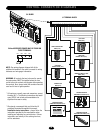
TRAFFIC
STREET
SAMS
Conduit
Second
COMPLEX
OR
PARKING LOT
Conduit
Terminal
Block
Terminal
Block
Shielded
Cable
(Twisted Pair)
Earthground Rod
(One Side Only)
Hold Open
Shadow Loop
Safety Loop