


1313
INSTALLATION
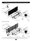
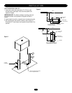
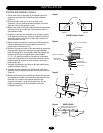
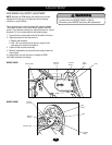
CONTROL ARM ASSEMBLY (SW490)
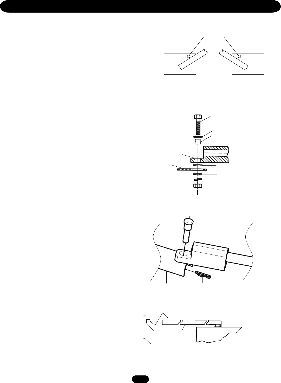
1. Set the control arm’s close stop on the operator so that its
position corresponds with the handling of the installation
(Figure 1).
2. Remove the open stop, as it is not to be used in this
application. Use any existing hardware necessary to seal the
open stop’s hole in the operator’s cover.
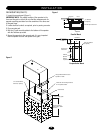
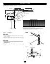
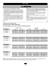
3. Measure the length of the gate panel and select the appropriate
extension arm (x) and control arm (Y) dimensions from the
gate installation table.
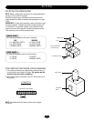
4. Install the control arm hub assembly to the operator’s output
shaft. Make sure that the key is properly inserted into the hub
assemblies keyway. Lock the key in place with using the set
screw provided in the hub.
5. Attach control arm extension to control arm hub assembly by
bolting or welding the two pieces together to achieve the
proper control arm dimension (Y).
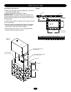
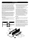
6. Determine the proper location of the gate bracket by measuring
the gate panel’s length and referring to the gate installation
table (Dimension B) on the next page. Install the supplied gate
bracket or install your own gate bracket (recommended
2" x 2" x 1/4" angle) horizontally on the gate and at the same
height as the top surface of the control arm extension. Secure
the gate bracket to the gate by either welding or bolting the
bracket to the gate.
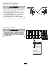
7. Assemble one extension arm holder to the gate bracket using
supplied hardware (Figure 2).
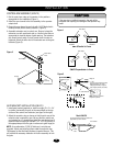
8. Assemble the other extension arm holder to the control arm
extension using the supplied pivot pin assembly and cotter pin
(Figure 3).
9. Measure and cut pipe (not provided) and position the pipe into
the extension arm holders to achieve the proper extension arm
dimension (X). Insert the hex head set screws in each
extension arm holder in order to hold pipe firmly. Do not
tighten until testing and all final adjustment have been
completed (Figure 4).
MODEL SW490
2"x2"x1/4"
angle
(by others)
gate
Control arm
extension
Figure 2
Figure 3
Figure 4
SW490 Parallel to Fence
Left hand
installation
Right hand
installation
Close Stops
Gate bracket or
extension arm
3/4"-10 x 3 Hex Head Bolt
Extension Arm Holder 3/4"
3/4" Bushing
3/4"-10 Hex Nut
3/4" Flat Washer
3/4" Flat Washer
3/4" Flat Washer
Extension arm holder
Extension arm
Cotter Pin
Pivot pin assembly
Bottom of angle and top of control
arm extension should be level
Control arm
extension
Figure 1
Split Lock Washer 3/4"