


2
2
OPERATOR SPECIFICATIONS
Carton Inventory . . . . . . . . . . . . . . . . . . . . . . . . . . . . . . . . . . . . . .2
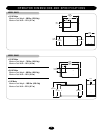
Operator Dimensions and Specifications . . . . . . . . . . . . . . . . . . .3
UL325 Model Classifications . . . . . . . . . . . . . . . . . . . . . . . . . . . .4
OPERATOR WARNINGS
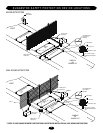
Suggested Safety Protection Device Locations. . . . . . . . . . . . . . .5
Safety Installation Information . . . . . . . . . . . . . . . . . . . . . . . . . . .6
Gate Construction Information . . . . . . . . . . . . . . . . . . . . . . . . . . .7
Safety for Swing and Ornamental Grill Type Gates. . . . . . . . . . . .8
Warranty Sign Placement . . . . . . . . . . . . . . . . . . . . . . . . . . . . . . .8
INSTALLATION
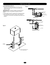
Post Mounting (SW470). . . . . . . . . . . . . . . . . . . . . . . . . . . . . . . .9
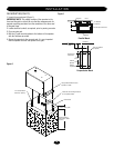
Pad Mounting (SW470) . . . . . . . . . . . . . . . . . . . . . . . . . . . . . . .10
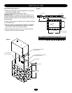
Pad Mounting (SW490) . . . . . . . . . . . . . . . . . . . . . . . . . . . . . . .11
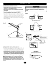
Control Arm and Gate Bracket Installation (SW470). . . . . . . . . .12
Control Arm Assembly (SW490) . . . . . . . . . . . . . . . . . . . . . 13-14
Manual Disconnect . . . . . . . . . . . . . . . . . . . . . . . . . . . . . . . . . . .14
WIRING
Power Wiring Installation . . . . . . . . . . . . . . . . . . . . . . . . . . . . . .15
On/Off Switch Power Wiring. . . . . . . . . . . . . . . . . . . . . . . . . . . .16
Stop/Reset Button Control Wiring . . . . . . . . . . . . . . . . . . . . . . .16
ADJUSTMENT
Programming the Radio Receiver. . . . . . . . . . . . . . . . . . . . . . . .17
Limit Switch Adjustment. . . . . . . . . . . . . . . . . . . . . . . . . . . . . . .18
RPM Sensor (Hall Effect) Adjustment. . . . . . . . . . . . . . . . . . . . .19
SAMS (Sequenced Access Management System) . . . . . . . . . . .20
Accessory Wiring . . . . . . . . . . . . . . . . . . . . . . . . . . . . . . . . . 21-22
Control Board Illustration . . . . . . . . . . . . . . . . . . . . . . . . . . . . . .23
Controller Programming and Features . . . . . . . . . . . . . . . . . 24-25
Program Settings . . . . . . . . . . . . . . . . . . . . . . . . . . . . . . . . . 26-27
TROUBLESHOOTING
. . . . . . . . . . . . . . . . . . . . . . . . . . .
28-29
MAINTENANCE
Operator Maintenance. . . . . . . . . . . . . . . . . . . . . . . . . . . . . . . . .30
Single Phase Wiring Diagram (SW470) . . . . . . . . . . . . . . . . . . .31
Single Phase Wiring Diagram (SW490) . . . . . . . . . . . . . . . . . . .32
Three Phase Wiring Diagram (SW490). . . . . . . . . . . . . . . . . . . .33
Control Connection Diagrams. . . . . . . . . . . . . . . . . . . . . . . . . . .34
Repair Parts and Illustrated Parts - SW470 . . . . . . . . . . . . . 35-36
Repair Parts and Illustrated Parts - SW490 . . . . . . . . . . . . . 37-38
Variable Parts - SW490 . . . . . . . . . . . . . . . . . . . . . . . . . . . . . . .39
Safety Accessories for Secondary Entrapment Protection . . . . .39
WARRANTY POLICY AND SERVICE
. . . . . . . . . . . . . . . . .40
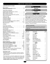
TABLE OF CONTENTS
IMPORTANT NOTE
• BEFORE attempting to install, operate or maintain the operator,
you MUST read and fully understand this manual and follow all
safety instructions.
• These instructions are intended to highlight certain safety related
issues. These instructions are not intended to be comprehensive.
Because each application is unique, it is the responsibility of the
purchaser, designer, installer and end user to ensure that the
total gate system is safe for its intended use.
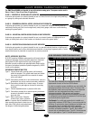
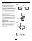
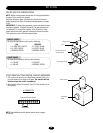
CARTON INVENTORY
Before beginning your installation check that all components were
supplied and received undamaged. Refer to list below for factory
supplied parts.
PART NO. DESCRIPTION QTY.
SW470
02-401-SP Stop Button 1
10-2108-T Arm Channel 1
10-2109 Extension Arm 1
10-2111 Gate Bracket 1
40-3505 Warning Sign 2
80-2103 Black Plastic Knob 2
82-HN38-18 3/8 x 1-1/2 Hex Head Bolt 2
82-SB50-08 1/2-13 x 1/2 Shoulder Bolt 2
84-FN-38 3/8-16 Serrated Flanged Nut 4
85-FW-38 3/8" Flat Washer 2
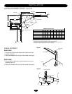
SW490
02-401-SP Stop Button 1
06-2025-T Arm Channel 1
08-2001 Extension Arm 2
10-2011 Gate Bracket 1
70-18618 Warning Sign 1
10-3900 39" Galvanized Steel Pipe 1
11-18619 Pivot Pin 1
12-10172 3/4 Bushing 2
40-18627 Label, Disconnect 1
40-3505 Warning Sign 2
80-207-20 3/8 x 3/8 x 1-1/2 Key 1
80-575 3/4 Flat Washer 4
82-HN38-16 3/8-16 x 1 Hex Head Bolt 2
82-HN75-28 3/4-10 x 3 Hex Head Bolt 1
82-NH38-06CP 3/8-16 x 3/8 Cone Point Set 6
84-RH-75 3/4-10 Hex Nut 1
85-LS-38 3/8 Lockwasher 2
86-CP05-300 Cotter Pin 2
HARDWARE KITS SW470 (K77-SW470) & SW490 (K77-SW490)
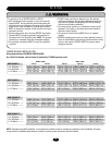
ATTENTION
AVERTISSEMENT AVERTISSEMENT
AVERTISSEMENT
WARNING WARNING
CAUTION
WARNING
WARNING
PRECAUCIÓN
ADVERTENCIA
ADVERTENCIA ADVERTENCIA
ATTENTION
AVERTISSEMENT AVERTISSEMENT
AVERTISSEMENT
WARNING
CAUTION
WARNING WARNING
WARNING
PRECAUCIÓN
ADVERTENCIA
ADVERTENCIA ADVERTENCIA
ATTENTION
AVERTISSEMENT AVERTISSEMENT
AVERTISSEMENT
WARNING
CAUTION CAUTION
WARNING
WARNING
PRECAUCIÓN
ADVERTENCIA
ADVERTENCIA ADVERTENCIA
Mechanical
Electrical
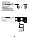
When you see these Safety Symbols and Signal Words on the
following pages, they will alert you to the possibility of serious
injury or death if you do not comply with the warnings that
accompany them. The hazard may come from something
mechanical or from electric shock. Read the warnings carefully.
When you see this Signal Word on the following pages, it will alert
you to the possibility of damage to your gate and/or the gate
operator if you do not comply with the cautionary statements that
accompany it. Read them carefully.