


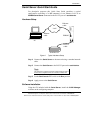
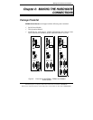

Making the Hardware Connections
Manual Documentation Number: ESR90x-0508m Chapter 2 11
B&B Electronics Mfg Co Inc – 707 Dayton Rd - Ottawa IL 61350 - Ph 815-433-5100 - Fax 815-433-5104 – www.bb-elec.com
B&B Electronics Ltd – Westlink Commercial Park – Oranmore, Galway, Ireland – Ph +353 91-792444 – Fax +353 91-792445 – www.bb-europe.com
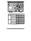
Serial Port(s)
• ESR901: One serial port with two connector options: one (DB-9M) or
one five-terminal removable terminal block (DIP switch selectable)
• ESR902: Two serial port connectors (DB-9M)
• ESR904: Four serial port connectors (DB-9M)
N
N
o
o
t
t
e
e
:
:
Refer to Appendices A, B and C for connection pin-outs.
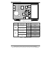
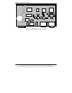
Power Connector
The power connector is a removable terminal block with four terminals.
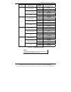
From top to bottom the terminals are:
Terminal Connect to Description
GND
Negative side of DC
power supply (if DC
power used)
Also connect negative
side of Backup DC
power supply (if used)
Internally, the chassis ground of the Serial
Server is connected to this terminal.
AC In
One side of AC power
supply (if AC power
used)
Either AC or DC power can be used to
power ESR Serial Servers. Power supply can
voltages range from 9 V to 48 VDC or 8 V
to 24 VAC.
AC/DC +
In
The other side of AC
power supply (if AC
power used)
OR
Positive side of DC
power supply (if DC
power used)
Backup
DC+ In
Positive side of
Backup DC power
supply
Backup power must be DC voltage and can
be any voltage between 9 VDC and 48 VDC.
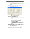
Serial Server/Port Operational Modes
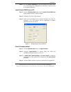
Using the ESP Manager, Web Server or Telnet the Serial Server can be put
into Console Mode, Default Mode or Upgrade Mode. The serial ports can be
configured for RS-232, RS-422, RS-485H (half duplex) or RS-485F (full
duplex) operation. The server also can be put into
Console Mode by placing
the Run/Console switch in the Console position.