


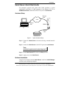
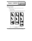

Making the Hardware Connections
10 Chapter 2 Manual Documentation Number: ESR90x-0508m
B&B Electronics Mfg Co Inc – 707 Dayton Rd - Ottawa IL 61350 - Ph 815-433-5100 - Fax 815-433-5104 – www.bb-elec.com
B&B Electronics Ltd – Westlink Commercial Park – Oranmore, Galway, Ireland – Ph +353 91-792444 – Fax +353 91-792445 – www.bb-europe.com
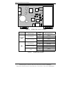
ESR90x Indicators, Switches and Connectors
Indicators
• One bi-color Link LED (Yellow = 10BaseT, Green = 100Base T)
• One green Ready LED (flashing = system ready)
• One red Power LED
• One red RX LED and one green TX LED for each serial port
Switches
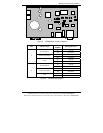
Reset
A recessed reset switch that allows the united to be reset. Insert a small
plastic tool, press lightly and hold for three seconds. The Link and Ready
lights will go out and then come back on.
Run/Console Switch
A recessed single DIP (dual inline package) switch that allows the Serial
Server to be switched between Run Mode and Console Mode. When
switched to the Console position the Serial Server enters Console Mode. This
allows you to configure the Serial Server from a PC running a terminal
program such as HyperTerminal without connecting the server to the
network. To communicate with the connected serial device the switch must
be returned to “Run” position.
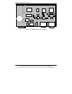
DB-9/Terminal Switch (ESR901 only)
Allows connection to the serial port (RS-232, 422 or 485) via the DB-9M
connector or the five-terminal removable terminal block.
Connectors
Ethernet Connector
One standard RJ-45 receptacle that allows the Serial Server to be connected
to an Ethernet hub, switch, or wall plate using a standard straight-through RJ-
45 (male) Ethernet cable. To connect directly to an RJ-45 Ethernet port on a
PC or laptop a crossover Ethernet cable must be used.