Chapter 3 Connector Pinouts
19
USB Connector
1
1
2
2
3
3
4
4
USB Connector
Universal Serial Bus Connector Pinouts
Pin Number Signal Description
1 VBUS
2 D+
3 D-
4 GND
NOTE Use of the USB port is supported for printers, scanners, and external modems.
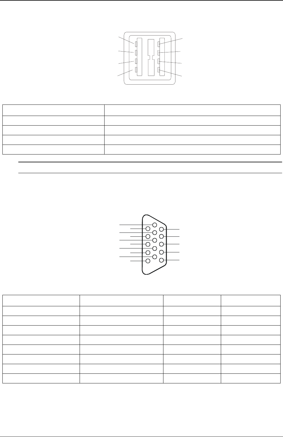
Video Connector
The embedded video uses the standard 15-pin analog display pinout configuration. The pinouts for your
monitor may vary. For the pinouts for your monitor, refer to the manual provided with your monitor.
1
2
3
4
5
6
7
8
9
10
11
12
13
14
15
Video Connector
Video Connector (female) Pinouts
Pin Number Function Pin Number Function
1 Red 9 Key (no pin)
2 Green 10 Sync return (ground)
3 Blue 11 Monitor ID bit 0
4 Monitor ID bit 2 12 Monitor ID bit 1
5 Monitor self test (ground) 13 Horizontal sync (+)
6 Red return (ground) 14 Vertical sync (-)
7 Green return (ground) 15 Not used
8 Blue return (ground)


