DM9161B
10/100 Mbps Fast Ethernet Physical Layer Single Chip Transceiver
Final 32
Version: DM9161B-12-DS-F01
January 31, 2008
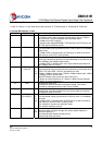
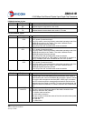
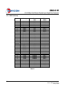
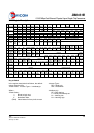
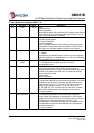
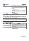
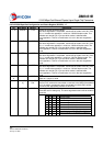
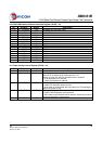
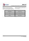
8.12 (Specified config) Register – 20
Bit Bit Name Default Description
20.15 TSTSE1 0,RW Vendor test select control
20.14 TSTSE2 0,RW Vendor test select control
20.13 FORCE_TXSD 0,RW Force Signal Detect
1: force SD signal OK in 100M
0: normal SD signal.
20.12 TSTSEL3 0,RW Vendor test select control
20.11 PREAMBLEX 0,RW Preamble Saving Control
1: 10M TX preamble bit count is normal.
0: when bit 10 is set, the 10M TX preamble count is reduced.
When bit 11 of register 29 is set, 10-bit preamble bit is reduced;
otherwise 20-bit preamble bits is reduced.
20.10 TX10M_PWR 0,RW 10M TX Power Saving Control
1: enable 10M TX power saving
0: disable 10M TX power saving
20.9 NWAY_PWR 0,RW N-Way Power Saving Control
1: disable N-Way power saving
0: enable N-Way power saving
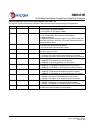
20.8 Reserved 0, RO Reserved
Read as 0, ignore on write
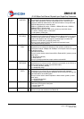
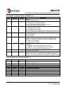
20.7 MDIX_CNTL MDI/MDIX,RO The polarity of MDI/MDIX value
1: MDIX mode
0: MDI mode
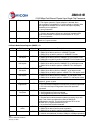
20.6 AutoNeg_dpbk 0,RW Auto-negotiation Loopback
1: test internal digital auto-negotiation Loopback
0: normal.
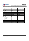
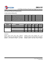
20.5 Mdix_fix Value 0, RW MDIX_CNTL force value:
When MDIX_DOWN = 1, MDIX_CNTL value depend on the register
value.
20.4 Mdix_do wn 0,RW MDIX Down
Manual force MDI/MDIX.
1: Disable HP Auto-MDIX , MDIX_CNTL value depend on 20.5
0: Enable HP Auto-MDIX
20.3 MonSel1 0,RW Vendor monitor select
20.2 MonSel0 0,RW Vendor monitor select
20.1 RMII_Ver 0,RW RMII version
1: support RMII 1.0
0: support RMII 1.2
20.0 PD_value 0,RW Power down control value
Decision the value of each field Register 19.
1: power down
0: normal
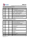
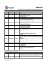
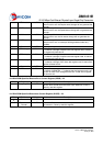
8.13 DAVICOM Specified Interrupt Register – 21
Bit Bit Name Default Description
21.15 INTR PEND 0, RO Interrupt Pending
Indicates that the interrupt is pending and is cleared by the current
read. This bit shows the same result as bit 0. (INTR Status)
21.14-21.
12
Reserved 0, RO Reserved