


English
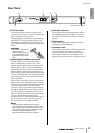
Front Panel
Owner’s Manual
11
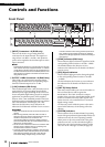
8 [SYNC] Indicators
These indicators show the operating status of the
Ri8-D/Ro8-D’s internal Dante network capability.
If the green indicator lights, the unit is operating as a
word clock slave and synching to the word clock.
If the green indicator flashes, the unit is operating as
the word clock master.
If the power to the unit is turned on but the green
indicator is turned off, the unit is not functioning
properly. In this case, refer to the “Messages” section
(see page 18).
If the orange indicator lights or flashes, refer to the
“Messages” section.
9 DIP Switches
These switches enable you to specify the settings
related to the startup operation of the unit.
Set the DIP switches while the power to the unit is
turned OFF. Otherwise, the setting will not be
effective.
Refer to the following for details.
• Switch 1 (UNIT ID)
This switch setting determines whether the
hexadecimal setting of the [UNIT ID] rotary switch
will range from 0 to F (0 to 15) or from 10 to 1F (16 to
31).
• Switches 2 and 3 (IP SELECT MODE)
These switches determine how the IP address is
specified during communication with the connected
computer or other devices.
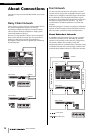
• Switch 4 (SECONDARY PORT)
This switch setting determines whether the rear-panel
[SECONDARY] connector will be used for a daisy
chain or redundant network.
With the [DAISY CHAIN] setting, you can connect
multiple Dante-enabled network devices in a daisy
chain without using a network switch. Refer to “Daisy
Chain Network” in the “About Connections” section
(see page 14) for more information about daisy chain
connections.
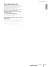
With the [REDUNDANT] setting, the [PRIMARY]
connector will be used for primary connections, and
the [SECONDARY] connector will be used for
secondary (backup) connections. If the unit is unable
to transmit signals through the [PRIMARY]
connector for some reason (e.g., due to damage or
accidental removal of the cable, or a failed network
switch), the [SECONDARY] connector will
automatically take over communications and
functions on the redundant network. Refer to “About
Redundant Networks” in the “About Connections”
section (see page 14) for more information on
redundant networks.
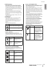
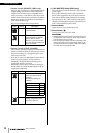
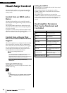
Switch Status
Represent a status with switch toggled up.
Represent a status with switch toggled down.
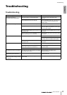
Switch Setting Description
UNIT ID
ranging from
0 to F
The setting range of the
[UNIT ID] rotary switch is
from 0 to F.
UNIT ID
ranging from
10 to 1F
The setting range of the
[UNIT ID] rotary switch is
from 10 to 1F.
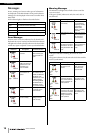
Switch Setting Description
AUTO IP Dante networks will
automatically assign the IP
address.
DHCP The IP address assigned
by the DHCP server will be
used.
STATIC IP
(AUTO)
The IP address will be set
to 192.168.0.xx (xx=UNIT
ID).
1
1
2
3
2 3
2
3
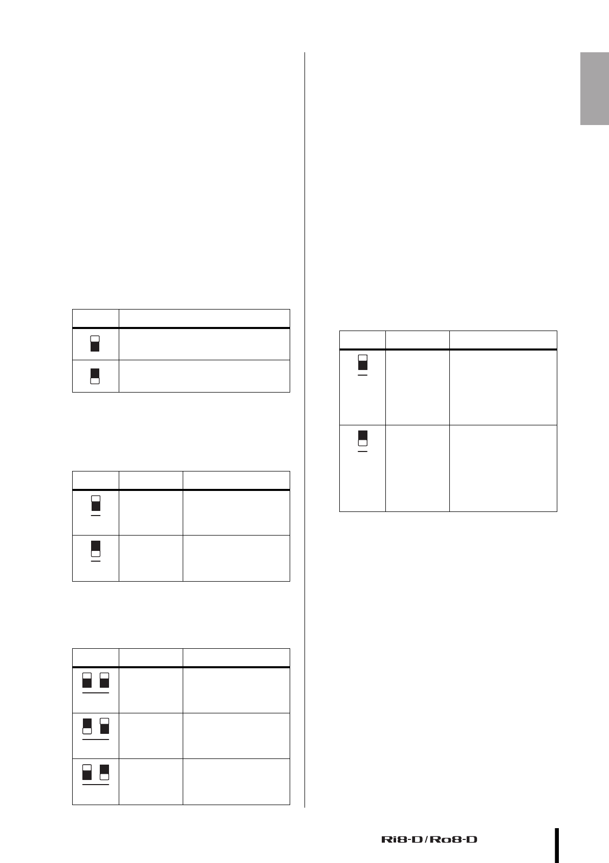
Switch Setting Description
DAISY CHAIN The [SECONDARY]
connector is used for a
daisy chain connection.
It can be connected in a
daisy chain by connecting
to [PRIMARY] connector of
the next device.
REDUNDANT The [SECONDARY]
connector is used for a
redundant network. It will
function as backup
connection, independent of
the network to which the
[PRIMARY] connector is
connected.
4
4