


Controls and Functions
Owner’s Manual
10
Controls and Functions
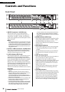
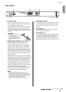
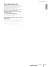
Front Panel
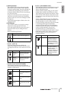
1 [INPUT] Connectors 1–8 (Ri8-D only)
These are the XLR-3-31 type analog balanced
connectors for the input channels. The input level
range is from –62 dBu to +10 dBu. +48V phantom
power can be supplied to devices that require it via the
input connectors.
NOTE
The PAD will be switched on or off internally when the gain
of the internal head amp is adjusted between +17 dB and
+18 dB. Keep in mind that noise may be generated if there
is a difference between the Hot and Cold impedance of the
external device connected to the INPUT connector when
using phantom power.
2 OUTPUT +4 dBu Connectors 1–8 (Ro8-D only)
These XLR-3-32 type balanced connectors deliver
analog output from the unit’s corresponding output
channels. Nominal output level is +4 dBu.
3 [+48V] Indicators (Ri8-D only)
These indicators light when +48V phantom power is
turned ON for the corresponding input channels.
Phantom power supply switching can be carried out
from a compatible digital mixing console or computer
application. No phantom power will be supplied,
however, if the [+48V MASTER] switch is OFF, even
if phantom power to individual channels is turned ON
(the +48V indicators will still light). The +48V
indicators also function as error indicators: the
indicators for all channels will flash if an error occurs.
CAUTION:
• Make sure that phantom power is turned OFF unless it is
needed.
• When turning phantom power ON, make sure that no
equipment other than phantom-powered devices such as
condenser microphones are connected to the
corresponding [INPUT] connectors. Applying phantom
power to a device that does not require phantom power can
damage the connected device.
• Do not connect or disconnect a device to an INPUT while
phantom power is applied. Doing so can damage the
connected device and/or the unit itself.
• To prevent possible damage to speakers, make sure that
power amplifiers and/or powered speakers are turned OFF
when switching phantom power ON or OFF. We also
recommend setting all digital mixing console output
controls to minimum when turning phantom power ON or
OFF. Sudden high level peaks caused by the switching
operation can damage equipment as well as the hearing of
those present.
4 [PEAK] Indicators (Ri8-D only)
These indicators light red when the signal level of the
corresponding channel reaches or exceeds –3 dBFS.
The PEAK indicators also function as error
indicators: the indicators for all channels will flash if
an error occurs.
5 [SIG] (Signal) Indicators
These indicators light green when the signal applied
to the corresponding channel reaches or exceeds
–34 dBFS.
The SIG indicators also function as error indicators:
the indicators for all channels will flash if an error
occurs.
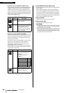
6 [UNIT ID] Rotary Switch
This rotary switch enables you to set an ID number so
that connected devices will recognize the
Ri8-D/Ro8-D. The UNIT ID must be a unique
number in the network so that the Ri8-D/Ro8-D will
be able to transmit and receive audio signals over a
Dante network, or be controlled from a connected
digital mixing console.
Use the rotary switch while the power to the unit is
turned OFF. Otherwise, the ID setting will not be
effective.
7 [SYSTEM] Indicators
These indicators show the Ri8-D/Ro8-D’s operating
status. If the green indicator lights steadily and the red
indicator turns off, the unit is operating normally.
When power to the unit is turned ON, if the green
indicator turns off, or if the red indicator lights or
flashes, the unit is not functioning properly. In this
case, refer to the “Messages” section (see page 18).
1
1 2 3 4 5 6 7 8
ON
1 2 3 4 5 6 7 8
ON
1
12 B3
4
5A
0
78
78
69