


9
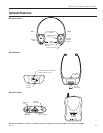
WIR TX75 Two-Channel Infrared Transmitter
MAN 166C
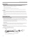
Connect Power
WARNING: MAINS VOLTAGE MUST NOT FALL BELOW 100VAC, 0R SYSTEM PERFORMANCE WILL BE
GREATLY REDUCED. UNIT MAY ENTER RESET MODE UNTIL POWER IS RESTORED.
1. Plug the power supply output cord into “Power In” on the WIR TX75.
2. Attach a line cord to the power supply.
3. Plug the power supply into the AC outlet. TFP 046: 100-240 VAC IN, 50 / 60 Hz.
This system is designed for class 2, low-voltage wiring. Always follow local electrical codes when using low-voltage wiring.
Green Power
The WIR TX75 is equipped with a sleep/power save feature. If no audio is present on either channel for three minutes, the
transmitter will automatically go into sleep/power save mode. This mode decreases power consumption by 80 percent. Units
will automatically start up when audio is activated. This sleep/power save feature can be disabled. Contact Williams Sound for
instructions.
On power up, the WIR TX75 performs a self-test to detect damage due to shipping, handling, tampering or incorrect operation.
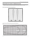
If any failure is present, green indicator lights will blink. See WIR TX75 Indicators table on page 12 for instructions on how to read
indicator lights.
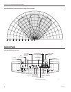
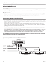
Connect Audio Source
Automatic Channel Detection/ Shutdown
The WIR TX75 offers two carrier frequencies: Ch 1 (2.3 MHz) and Ch 2 (2.8 MHz). The WIR TX75b offers two different carrier
frequencies: Ch 1 (3.3 MHz) and Ch 2 (3.8 MHz). Either unit automatically detects the presence of audio on the microphone and RCA
audio inputs, and transmits on either/both channels when an audio signal is present on that channel. If audio is present on both the
microphone and RCA jack for a given channel, the audio signals will be mixed.
When no audio signal is present on a channel for three minutes, the TX75 will shut down that channel. Operating the WIR TX75 in single-
channel mode provides a 40 percent increase in range over two-channel mode.
Line Level Source:
The WIR TX75 will accept line level, balanced or unbalanced audio inputs. Select the frequency(ies) you wish to transmit on and
connect your audio source(s) to the appropriate jack(s). If your audio inputs are balanced, use the switch to select “bal”. If your
audio inputs are unbalanced, use the switch to select “unbal”. See gure 7 for balanced wiring conguration.
Microphone Source
Plug an electret microphone into the 3.5mm “Mic In” jack (MIC 027, MIC 100, or MIC 090). To assign the microphone to Ch 1
use the Mic Channel Switch to select “2.3” (or “3.3” MHz on the TX-75b). To assign the microphone to Ch 2 use the Mic Channel
Switch to select “2.8” (or “3.8” MHz on the TX-75b).
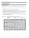
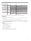
Figure 7: Balanced line out (XLR) to WIR TX75 line input (RCA) cable
1 23
FEMALE XLR
RED (IN PHASE)
RED
RCA
(TIP=IN PHASE)
2 CONDUCTOR
WITH SHIELD
BLACK (SIGNAL)
BLACK
TO TX75
SHIELD NOT CONNECTED
ON TX75 CABLE END
1= SHIELD, 2= RED (SIGNAL IN PHASE), 3=BLACK (SIGNAL)
A160