


6
WIR TX75 Two-Channel Infrared Transmitter
MAN 166C
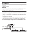
Installation Procedures
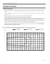
Determine Coverage Area
When using the WIR TX75 transmitter in single-channel mode with the RX22-4 receiver, the system coverage area will exceed
5000 ft² (185 m²). WIR TX75 units automatically adjust to give the best coverage area possible in both 1-channel and 2-channel
modes.
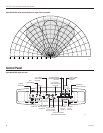
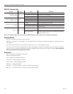
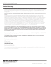
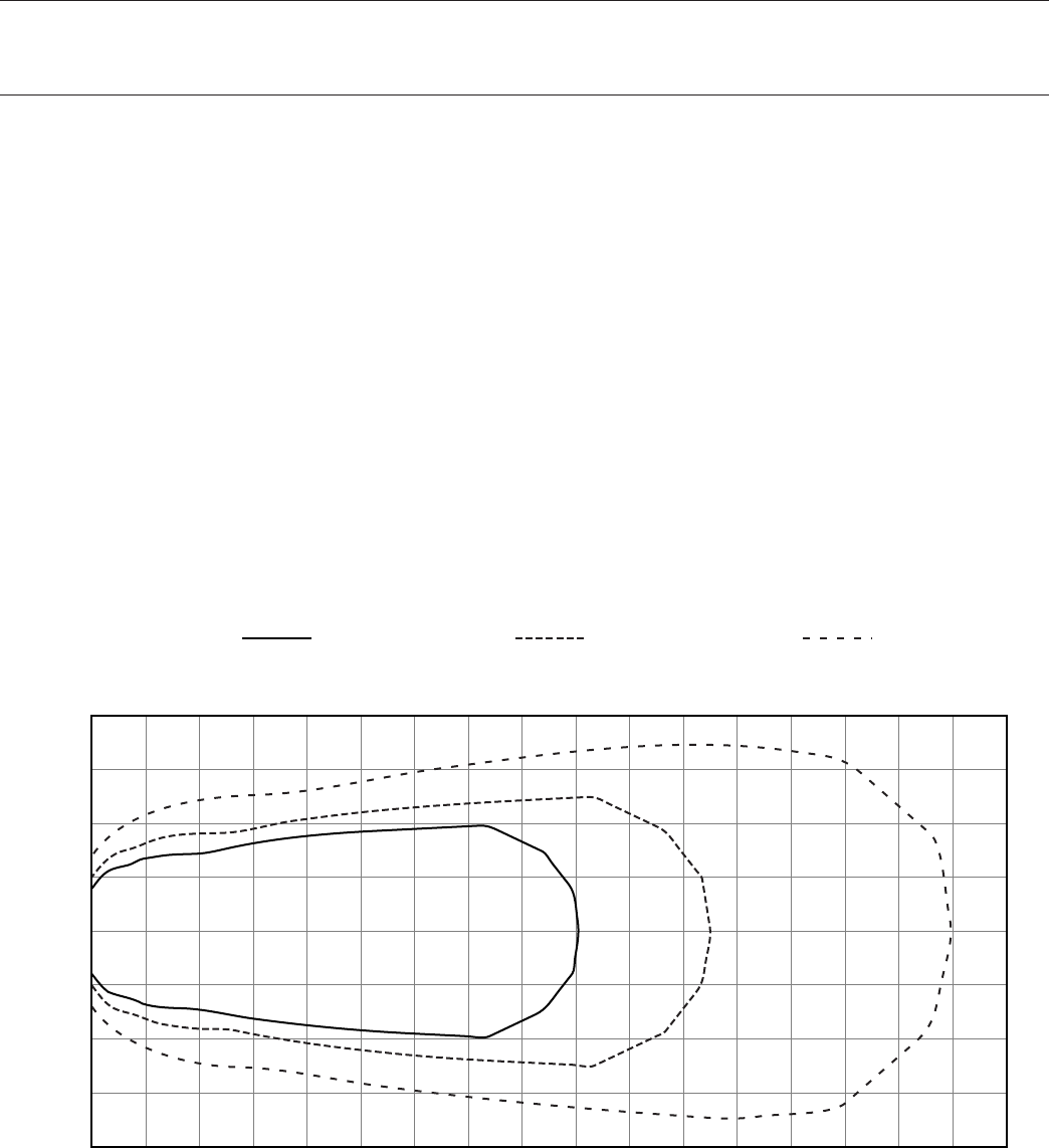
Figure 1 illustrates typical coverage pattern for the TX75. This can be affected by direct/indirect sunlight, reections on walls and
room construction.
Reections of the infrared light from walls, ceilings, and oors may change these patterns.
Important: Remember to point the transmitter towards the listening audience.
Remember: Most objects block infrared light. The transmitter cannot be concealed behind walls, glass, curtains, etc.
These patterns are the direct radiation pattern. The infrared radiation does not drop to zero outside the illustrated patterns; it
decreases. It still may be useable at a greater distance, depending on the receiver sensitivity and the reective characteristics of
the room. Reections of the infrared light from walls, ceilings, and oors may change these patterns.
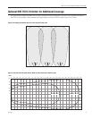
The TX75 and TX75-S can be operated with or without the faceplate, if desired. The faceplate can be removed and painted to
match room decor. Lightly sand faceplate with 400 grit sandpaper apply primer and two coats of nal color. Do not paint the
infrared lens behind the faceplate of the TX75.
Figure 1: Receiver coverage area with WIR TX75 transmitter OR WIR TX75-S slave emitter in single channel mode.
0
10
20
30
40
RX22-4 RECEIVER
RX18 RECEIVER
RX15-2 RECEIVER
0 10 20 30 40 50 60 70 80 90 100 110 120 130 140 150 160 170
A157
FEET