


10
WIR TX75 Two-Channel Infrared Transmitter
MAN 166C
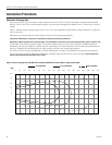
Adjust the Audio Level
Line Level Source
After an audio signal has been connected to the transmitter, adjust the audio source gain until the WIR TX75 audio-level indicator
for that channel blinks periodically.
Microphone Source
Speak into the microphone from a normal distance and at a natural voice level. Use the microphone gain adjustment on the TX75
to set the gain to the point where the audio level indicator on the selected channel blinks periodically. If the audio level indicator is
always on or on most of the time, the level is too high. If the audio level indicator is never on, the level is too low.
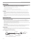
Connecting Master and Slave Units
Connect all WIR TX75 master and slave(s) units together using CAT-5e cables, the “to slave” jacks on the master, and the “Master
In” jack on the slave(s). For systems with no slave units, the CAT-5e cables and “to slave” jacks are not used. For systems with one
slave unit, either “out 1” or “out 2” may be used.
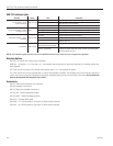
When a cable is plugged into a “to slave” jack, the master unit will automatically detect mis-wired, intermittent or bad CAT-5e
cables; a yellow status indicator light will blink on that channel’s “to slave” jack to indicate any problem. See WIR TX75 Indicators
table on page 12 for instructions on how to read indicator lights.
The WIR TX75 automatically detects when slave units are plugged in, establishes a data link to verify operation, monitors status,
and enables baseband output to the slave emitter(s).
Once a master and slave unit are connected, the yellow and green indicators located on the “to slave” and “Master In” jacks mimic
each other. This allows the user to know the status of the entire system by simply looking at the indicators on the back of the
master unit. A switch is provided to turn off all indicator lights AFTER initial set-up, to allow for less conspicuous operation.
Note: The WIR TX75 will automatically detect and adjust for differences in CAT-5e cable length. Matching cable lengths to the
slaves is not necessary. Cable length up to 100 feet may be used.
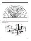
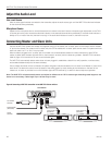
Figure 8: Connecting a WIR TX75 transmitter to two WIR TX75-S slave emitters
POWER
RCAMIC CAT5E
TX75 MASTER
TX75S SLAVE #1
(OPTIONAL)
AUDIO
SOURCE
MICROPHONE
(ELECTRET)
AC POWER
SOURCE
TX75S SLAVE #2
(OPTIONAL)
A161