


10 S1A10386 10/2009
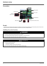
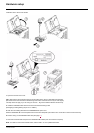
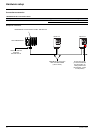
Hardware setup
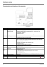
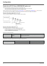
Characteristics and functions of the terminals
Terminal Function Electrical characteristics
R2A
R2B
R2C
Configurable relay outputs:
1 relay logic output, one “N/C”
contact and one “N/O” contact
with common point.
• Minimum switching capacity: 10 mA for 5 V
c
• Maximum switching capacity on resistive load (cos ϕ = 1 and L/R = 0 ms):
5 A for 250 V
a and 30 V c
• Maximum switching capacity on inductive load (cos ϕ = 0.4 and L/R = 7 ms):
2 A for 250 V
a and 30 V c
• Sampling time: 8 ms
• Service life: 100,000 operations at maximum switching power
COM Analog I/O common 0 V
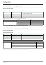
+10 Power supply for reference
potentiometer (2.2 to 10 k
Ω)
• +10 V (+ 8% - 0%)
• 10 mA max
• Protected against short-circuits and overloads
AI2 Analog voltage input Bipolar analog input 0 ± 10 V (maximum safe voltage ± 30 V)
The + or - polarity of the voltage on AI2 affects the direction of the setpoint and
therefore the direction of operation.
• Impedance: 30 k
Ω
• Resolution: 0.01 V, 10-bit + sign converter
• Precision ± 4.3%, linearity ± 0.2%, of maximum value
• Sampling time: 8 ms
• Operation with shielded cable 100 m maximum
AI3 Analog current input Analog current input X-Y mA by programming X and Y from 0 to 20 mA:
• Impedance: 250
Ω
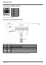
+24 Logic input power supply • + 24 V protected against short-circuits and overloads, minimum 19 V, maximum 30 V
• Maximum customer current available: 100 mA
LI1
LI2
LI3
Logic inputs Programmable logic inputs
• Impedance: 3.5 k
Ω
• + 24 V internal or 24 V external power supply (min. 19 V, max. 30 V)
• Max. current: 100 mA
• Max. sampling time: 4 ms
Source position: Positive logic State 0 if < 5 V or logic input not wired, state 1 if > 11 V
RJ45 Communication port Connection for SoMove software, Modbus, remote display, loader tools.
SW1 Addressing switches See page 14
.
SW2 Line termination switches See page 11
.
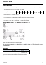
PROFIBUS
DP
Communication PROFIBUS DP open style connector for connection to the fieldbus, see page 11
.