3
Step 3.
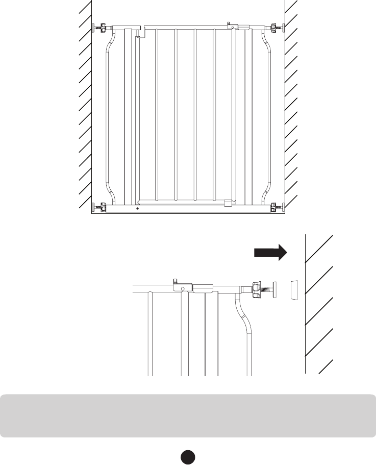
Diagram C1
Diagram C2
HINT:
It may be necessary to hold the Threaded Spindle Rods or Rubber
Feet while rotating the Adjustment Wheels to ensure the entire
unit does not rotate.
Position the gate so that it is level and centered within your doorway or opening.
Rotate the adjustment wheels on the threaded spindle rods in the opposite direction
as in Step 1, expanding the gap between the rubber foot and the adjustment wheel.
Expand each of the 4 Threaded Spindle Rods until they make contact with the
doorway or opening. Do not fully tighten the Threaded Spindle Rods yet.


