Front End Board
52 Chapter 6 Theory of Operation
Front End Board
M1351A
(M1353-66501
and
M1353-66511)
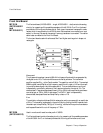
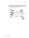
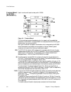
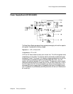
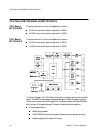
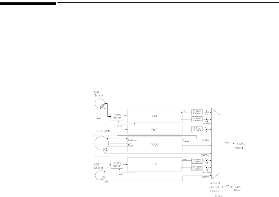
The Frontend board (M1353-66501 − single, M1353-66511 - dual) contains the analog
circuitry for measuring all the possible parameters of the M1351A. One IC on the board
provides the US timing and window control. Each type of transducer has a specific mode
resistor which is recognized by the M1351A when the transducer is connected to an input
socket. In this way, the user can be warned if a wrong transducer is connected. The marker
cable is also connected to the Front End Board.
The frontend boards used with software at Rev E and higher are triangular in shape, not
rectangular.
Ultrasound
The ultrasound transducer transmits 998.4kHz ultrasound bursts which are generated by
the digital control ICs. The burst widths are controlled by software. The transmitter
amplifier supplies 5V
pp
_ at the Cardio sockets. The repetition rate is 3.2kHz. The received
998kHz signal is amplified by a high frequency amplifier with a gain of 120 and then split
to provide a reference path
a and a compare path b. The two demodulators a and b are
independently controlled by software in their receive windows by the control ICs. The
demodulated LF signals are bandpass filtered (100 to 450Hz) and amplified by a software
controlled gain of 180 to 1860 in eight steps. The FMP-LF path is independently
demodulated, bandpass filtered and amplified by a factor of 18.
Toco
The excitation voltage is a biphase 2.4kHz rectangular continuous wave with an amplitude
of 5V
pp
. The frequency is generated in the control chip by dividing the 4MHz system clock.
the sense input is amplified by 786 (5
µ;V/V/mmHg), rectified with a synchronous detector
and lowpass filtered with a cut-off frequency of 7.5Hz.
M1353A
(M1353-66512)
Used in monitors with serial number prefix ≤ 3652G.
The Frontend board contains the analog circuitry for measuring all the possible parameters
of the M1353A. An IC on the board provides the US timing and window control, and


