


•PEG PEREGO® thanks you for choosing this
product.For over 50 years,PEG PEREGO has been
taking children for an outing:first with its famous
baby carriages and strollers,later with its pedal and
battery operated toy vehicles.
•Read this instruction manual carefully to learn the
use of the vehicle and to teach your child safe and
enjoyable driving.Please keep this manual for use
as a reference in the future.
•Our toys conform with the safety requirements
provided by the Council of the EEC,of the T.Ü.V.;of
the I.I.S.G.Istituto Italiano Sicurezza Giocattoli,and
the U.S. Consumer Toy Safety Specification F963.
•Peg Perego reserves the right to modify or change
its product.Price,literature,manufacturing
processes or locations or any combination of the
above mentioned entities may change at any time
for any reason without notice with impunity.
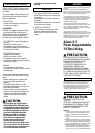
Years 3-7
Weight capacity
75 lbs
CAUTION:
ELECTRIC VEHICLE NOT
RECOMMENDED FOR CHILDREN
UNDER 3 YEARS OF AGE. AS WITH
ALL ELECTRIC PRODUCTS,
PRECAUTIONS SHOULD BE
OBSERVED DURING HANDLING
AND USE TO PREVENT ELECTRIC
SHOCK. RECHARGER INCLUDED.120
VOLTS, 60Hz,30W INPUT, 12 VOLTS
(DC) OUTPUT.
PEG PEREGO offers after-sales services,directly or
through a network of authorized service centers for
repairs or replacement parts.See the back cover of
this instruction manual for a list of service centers.
CAUTION:
ADULT ASSEMBLY REQUIRED.
USE CARE WHEN UNPACKING AS
COMPONENTS TO BE ASSEMBLED
MAY POSE A SMALL PARTS/SHARP
EDGE HAZARD.
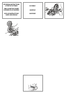
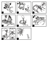
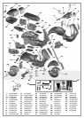
ASSEMBLY
1 • Turn the article upside down so that you can
work on the bottom of it.Remove the two
bushings from the axle.
2 • Position the training wheels as shown in the
figure.NOTE:Kick stand must be in “up”position
when attaching training wheels.Training
wheels are made specifically for each side,
notice that training wheel for left side has area
to allow for clearance of kickstand.
3 • Fasten the training wheels with the supplied
screws.
4 • Put the front wheel on the axle,keeping the
side with the plastic bearing on the inside.
5 • Put a stud into the included push tool,and
fasten the wheel in place,hammering it all the
way down.
6 • Slip the fender bushing onto the axle and push
it all the way to the end (picture B).NOTE:The
bearing is shaped so that it can only be put on
the axle one way (see detail in picture A).
7 • Slip the fender onto the axle and fasten it to
the fender bushing,as shown in the detail.
NOTE:Fender will only correctly fit onto
bushing one way.
ENGLISH
CUSTOMER SERVICE
ASSEMBLY INSTRUCTIONS
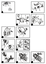
8 • Push the lower steering bearing all the way into
its hole,taking care to line it up correctly.
9 • Attach the axle unit with the wheel to the front
of the vehicle and fasten the fender to the
lower steering bearing.
10 • Attach the upper steering bearing.
11 • Attach the two black plastic trim pieces to the
body,as shown in the figure.
12 • Attach the foot mat,snapping it into the back
openings first and then the front openings
(bending the mat slightly). Press the central
part of the mat on both sides to fasten it
securely.
13 • Attach the handlebars and fasten them with
the supplied screw.
14 • Stick the mirrors into their holes on the
handlebars and turn them outwards to fasten
them into place.
15 • Lift the seat and place the carrier on the
vehicle. Fasten it with the four supplied screws.
16 • To connect the cover and the bottom of the
rear cargo box,align the black hinges with the
green clasps as shown in the figure and
squeeze together until they engage with a
“snap”.
17 • Position the cargo box on the rear rack and
insert the black plastic screw into one of the
two holes based on the height of your child.
18 • Using a screwdriver,securely fasten the cargo
box to the rear rack.
19 • Lower the seat.
20 • Turn the seat lock behind the seat to the
position shown in picture A. With the clasp in
the position shown in picture B,the seat can be
opened.
21 • Attach the taillight decal and snap the glass
cover into place.
22 • Attach the silver rear signal light decal,and
snap the glass covers into place.
23 • Attach the silver front signal light decal,and
snap the glass covers into place.
24 • Lift the seat and loosen the screw on the cover
inside the compartment under the seat.
Remove the cover.
25 • Connect the plugs and put the cover back.
Fasten the screw. Always remember to lower
the seat and to fasten it,after working in the
compartment under the seat. The vehicle is
ready for use.
INSERTING BATTERIES
To insert the batteries that run the lights and
electronic audio signals,follow these instructions:
26 • Loosen the screw on the battery cover on the
dash.Remove the cover.
27 • Remove the battery housing and insert two
1.5V AA batteries.(Batteries do not come with
vehicle.) Put the battery housing back into the
dash.
28 • Put the cardboard dashboard into place,
replace clear plastic cover and secure into place
with screw.
VEHICLE FEATURES AND INSTRUCTIONS FOR
USE
29 • A: Accelerator pedal.
B: brake pedal.
30 • SECOND SPEED:Lift the saddle up (fig.19) and
unscrew the under-seat space door (fig.24).
Select the speed by pressing the button:the
second speed is activated when the pressed
button reads number 2 at the top.
31 • C:Front light and horn button
D:Blinker button
E:Engine roar button
F:BOOSTER button.If the button is held down
while in motion,the vehicle proceeds in 2nd
speed.WARNING:this button only works if the
2nd speed button located under the seat has
been activated,as indicated in figure 30.
32 • The kickstand is only for use when the training
wheels have been removed.NOTE:Please be
sure your child has developed an adequate
sense of balance on the scooter before
removing the training wheels.Show your child
how to use his/her foot to lower the kickstand
into position by pushing down and to raise it
before riding by pulling up.
33 • Front carrier compartment.
34 • Rear carrier case.To open the cargo box,push
in on the button and at the same time pull up
on the cover.Maximum weight capacity of
cargo box:6.6 lbs/3Kg.
REPLACING THE LIGHT BULBS (2.5 Volt)
35 • Remove the front plastic headlight cover,using
a tool to lift it. Gently pull on the light bulb,to
extract the light socket. Unscrew the burnt
light bulb from the socket and replace it.Push
the light socket back to its original position and
put the plastic headlight cover back,as shown
in the figure.
36 • Remove the plastic turn-signal cover from the
burnt light,using a tool to lift it. Gently pull on
the light bulb,to extract the light socket.
Unscrew the burnt light bulb from the socket
and replace it.Push the light socket back to its
original position and put the plastic turn-signal
cover back,as shown in the figure.
REPLACING THE BATTERY
37 • Turn the red plastic seat lock behind the seat to
open it.Lift the seat.Loosen the safety screw on
the cover inside the compartment under the
seat,and disconnect the plugs.Turn the vehicle
upside down to work on the bottom of it.
Unscrew and remove one of the training
wheels.Remove the axle.
38 • While holding the kickstand,use the included
metal wrench to loosen and remove the nut
and washer opposite the kickstand.
39 • Remove the kickstand.NOTE:it will be
necessary to twist the kickstand as it is pulled
out.
40 • Lift the cover.
41 • Remove the dead or damaged battery.Push the
plug on the new battery through the hole in
the bottom,so that you can connect it to the
electrical system once you turn the vehicle
right-side-up.Place new battery into position
42 • Put the cover back on the battery
compartment.Reinsert the kickstand (again,it it
will be necessary to twist the kickstand as it is
inserted).NOTE:Be sure to properly align the
spring tab completely into the slot as shown in
figure A.Replace the washer (figure B) and
secure the kickstand in place by affixing and
tightening the nut.Slip the axle back into place.
Put the training wheel back on and fasten it
with the screw.
43 • Set the vehicle back on its wheels and connect
the plugs.Put the cover back on the
compartment under the seat and fasten the
screw. Lower the seat and fasten the red plastic
seat lock.
BATTERY RECHARGE
WARNING:
WARNING: BATTERY CHARGING
AND ANY OTHER OPERATION ON
THE ELECTRICAL SYSTEM MUST BE
CARRIED OUT BY ADULTS ONLY.
THE BATTERY CAN ALSO BE CHARGED
WITHOUT REMOVING IT FROM THE
VEHICLE.
44 • Disconnect electrical system plug A from
battery plug B,by pressing on the sides of both
plugs.
45 • Plug the battery charger into an electrical
outlet,following the instructions for the battery
charger.Connect plug B to plug C from the
battery charger.
46 • When the battery has finished charging,unplug
the battery charger from the electrical outlet,
then disconnect plugs C and B.
47 • Connect plugs B and A,pressing until they snap
together.Always remember to lower and to
fasten the seat when you have finished working
under it.
Before riding, charge your batteries
for 18 hours to initiate them.Failure to
do this will result in permanent
battery damage.
CAUTION:
Only adults should recharge
batteries,never children.
Never allow children to handle
batteries.
Only use the batteries specified by
the manufacturer. Only use the
charger specified by the
BATTERY MAINTENANCE
AND SAFETY