


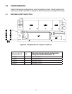

8
4.4 SIGNAL INPUTS
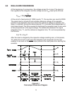
RATIO: The reference input allows an external voltage to be used as the
reference source for conversion. In this mode, the meter reads the ratio of the
signal voltage to the reference voltage rather than the true value of the input.
Signal Voltage
Reading in Counts =
Reference Voltage
x 10000
On the 20 V and 200 V ranges, the signal voltage must be scaled by 1/10 and
1/100, respectively. For all ranges, the standard reference input impedance ratio
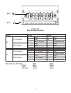
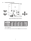
is 80 ohm. For 100 Mohm, open solder switch F on the main board (Figure 5.3).
The reference voltage must be between the limits specified, +0.5 to +2.0 V, and
must be positive with respect to analog ground.
HOLD: When high (or open), the A/D will free-run with equally spaced
measurement cycles every 40,002 clock pulses. If taken low, the converter will
complete the full measurement cycle and then hold this reading as long as HOLD
is low. A positive pulse (greater than 300 ns) will now initiate a new measurement
cycle, beginning with between 9,001 and 10,001 counts of auto-zero time. If the
pulse terminates before the full measurement cycle (40,002 counts) is complete,
it will not be recognized and the converter will simply complete the present
measurement. An external indication that a full measurement cycle has been
completed is that the first strobe pulse will occur 101 counts after the end of
this cycle. Thus, if HOLD has been low for at least 101 counts, the converter is
holding and ready to start a new measurement when pulsed high.
BLANKING: The display may be blanked by grounding the BLANKING input.
The blanking input must be open for normal display operation. The polarity sign
and decimal points are not blanked, but they will flash if the displayed reading
exceeds ±19999 counts.