


5
4.0 POWER AND SIGNAL
AC versions of the voltmeter are factory-set for 115 Vac in the USA and 230 Vac in
Europe (using C1 option) ±15% operation. DC versions are preset for 9-32 Vdc or
26-56 Vdc operation. It is not possible to change the meter from 9-32 Vdc to
26-56 Vdc or vice versa. Different static inverters are installed by the factory.
Refer to Safety Considerations prior to connecting power.
4.1 CHANGING OPERATING VOLTAGE
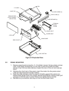
Remove power lines from the meter, then remove the meter from the case.
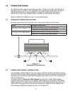
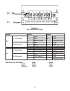
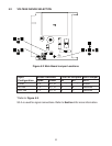
Figure 4.1
Side View of Transformer
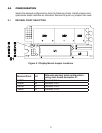
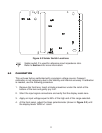
4.2 POWER AND SIGNAL CONNECTIONS
Use shielded, twisted cable for the input signal, with the shield terminated to analog
ground at the connector. Both analog and digital ground are internally connected and
should not be connected externally. For proper grounding, connect the low signal to
SIG LO (signal low).
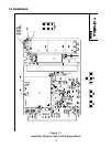
A jumper at S3-A (Figure 5-2 Main Board) ties SIG LO to ANA GND (analog
ground) internally. The common for digital inputs/outputs is connected to DIG GND
(digital ground). This allows current to flow only in the digital ground and prevents IR
drop in the analog ground that would be misread as a signal. A small voltage may
exist between analog and digital grounds on connector J1.
Input Jumper Installation
230 Vac ±15% (Option C1)
Remove W8 and W9 on the transformer
Install W4 on the printed circuit board
115 Vac ±15% (Standard)
Remove W8 and W9 on the transformer
Install W4 on the printed circuit board