


23
GS748T Gigabit Smart Switch
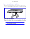
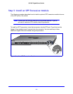
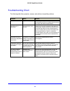
Step 4: Connect Devices to the Switch
The following procedure describes how to connect computers to the switch’s RJ-45 ports.
The GS748T contains Auto Uplink technology, which allows the attaching of devices using
either straight-through or crossover cables.
Figure 7. Connect Devices to the Switch
Connect each computer to an RJ-45 network port on the Switch front panel (
Figure 7
). Use
Category 5 (Cat5) Unshielded Twisted-Pair (UTP) cable terminated with an RJ-45 connector
to make these connections.
Note: Ethernet specifications limit the cable length between the switch and
the attached device to 100m (328 ft.).
LED Link/Act Mode Green=Link at 1000M Yellow=Link at 100/10M Blink=ACT
Power
Reset
Facto ry
Default
1
2
3
4
5
6
7
8
9
10
11
12 2213 14 15 16 17 18 19 20 21
23
24 3425 26 27 28 29 30 31 32 33
35
36 37 38 39 40 41 42 43 44
46T
45T
48F
47F
50
49
Combo
Ports
GS748T
SFP LED
GREEN=
100/
1000Mbps
Blink=ACT
48T
47T
``