


SCC-TC Series Thermocouple Input Modules User Guide 6 ni.com
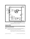
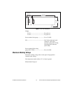
temperature measurements. To make this conversion, complete the
following steps:
1. Measure the thermocouple voltage.
a. Read the thermocouple channel on the E/M Series DAQ device
V
ESERIES
[CH(X)].
b. Calculate the thermocouple voltage by using the following
formula:
where
V
TC
is thermocouple voltage.
V
ESERIES
is E/M Series DAQ device voltage.
This step provides proper scaling for the thermocouple amplifier in the
SCC-TC0X.
2. Measure the reference-junction (cold-junction) temperature.
a. Read the thermistor voltage [AI (X+8)].
b. Convert the thermistor voltage to cold-junction temperature using
the formula in the Cold-Junction Sensor section.
3. Calculate the cold-junction compensation voltage by converting the
cold-junction temperature from step 2 to a thermocouple voltage. Use
the polynomial expressions applicable to the type of thermocouple you
are using.
4. Apply the cold-junction compensation to the thermocouple reading
by adding the cold-junction compensation voltage from step 3 to V
TC
.
5. Calculate the thermocouple temperature by converting the voltage
result from step 4 to a temperature. Use the polynomial expressions
applicable to the type of thermocouple you are using. This calculation
gives you a linearized temperature measurement.
Note Polynomials are from NIST Monograph 175.
Uncompensated Connectors and Accuracy
If you are using an SCC-TC02 with an uncompensated SCC panelette,
temperature gradients between the module and the junctions on the
panelette affect the accuracy of the measurements.
V
TC
V
ESERIES
100
---------------------=