8
STAGE D: ADDING THE HULL DETAILS
1. General Notes
Don’t forget to file off any flash on Britannia
metal fittings, clean the fittings and then prime
them with gr
ey primer before final paint.
Locate deck fittings and place them into
position. This can be done by measuring
from mast holes, station lines and centerline
(tick off from plans). Next, mark their posi-
tions by drilling holes into the deck and
inserting locating pins or dowels which will
be inserted into holes that you will need to
drill into each deck piece. Before permanent
installation, paint them according to the
Dapper Tom color scheme or your choice of
color. Having been pre-fitted, and with the
pins in place, they will be easy to put back
where they belong.
If wooden parts are not painted prior to
installation, at least make sure you have the
part sanded and ready for painting in place.
Use as little glue as necessary on parts. Watch
out for that glue squeeze-out. It’s hard to
remove if left to harden.
2. Transom Rail, Mouldings,
Counter Detail, & Main Boom
Sheet Rod
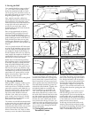
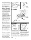
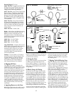
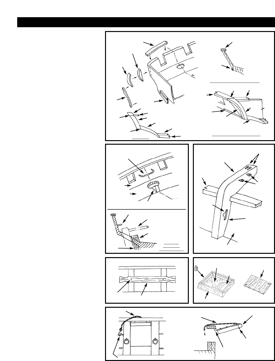
The transom rail (or taffrail as it is generally
called) curves both fore and aft and across the
top and sides of the transom so it is best cut
out of a wider piece of stripwood. Some steam
bending may be required at the side corners,
or the side rail portion can be cut to shape
from a wider block.
The transom extends beyond the sides of the
hull. This extension is not a part of the
machine-carved hull, so you first must add
the extension before installing the rails.
On the sides, the rail meets a fashion piece
that curves down to the waterway strip and
wale. Along the bottom of the transom out-
boar
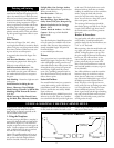
d, add a moulding strip
. F
igur
e D-1
should clear up this often confusing area.
I
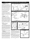
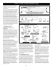
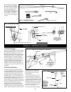
nboard on the counter, there is a a small
block to be added on centerline just for
war
d
of the rudder post opening. This is actually
the top of the sternpost on a r
eal ship. On the
transom, fit the main boom sheet traveler rod
made from wire. See Figure D-2 for a sketch
of the ar
ea.
3. Catheads, Bulwark Sheaves,
Cavils, & Gunport Lids
When y
ou installed the bulwar
k stanchions
earlier, most of the bow timbers and hawse
holes w
er
e finished at that time.
There are
still a few more details for the bulwarks
unless you got these done while installing the
bulwar
k stanchions.
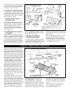
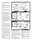
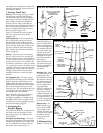
The catheads are laser cut parts. Before
installing, drill the holes for the anchor tackle
and add the eyebolts for the jibboom guys
(F
igur
e D-3).
FIG.
D-1 TRANSOM RAIL & FASHION PIECE
FIG. D-2 INBOARD STERN DETAILFIG. D-2 INBOARD STERN DETAIL FIG. D-3 CATHEADS
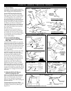
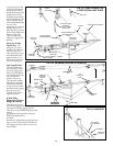
FIG.
D-4 CA
VILS
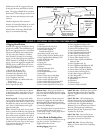
FIG. D-6 LADDER WAY
TAFFRAIL
TAFFRAIL
SIDE
TAFFRAIL
MOULDING
STRIP
F
ASHION
PIECE
TRANSOM
EXTENSION
PIECE
JOINT
CAP
RAIL
SIDE
T
AFFRAIL
WALE
W
ALE
JOINT
TRANSOM
COUNTER
DECK
DRILL
HOLES
FOR
ANCHOR
TACKLE
EYEBOLTS
FOR
JIBBOOM
GUYS
LASER-CUT
CA
THEAD
CLEAT FOR
BELAYING
ANCHOR
TACKLE
THIS SIDE OF
CATHEAD MAY
BE SHAPED TO
FIT FLUSH
AGAINST
BULWARK
CAP RAIL
BULWARK
HOOK TO EYEBOLT ON SIDE OF STANCHION
CL
BOOM SHEET
TRAVELER ROD
JOINT
F
ASHION
PIECE
T
AFFRAIL
CAP RAIL
SIDE TAFFRAIL
FASHION PIECE
WATERWAY STRIP
W
ATERWAY
STRIP
SECTION THROUGH TRANSOM
OUTBOARD VIEW AT CORNER
SIDE VIEW
TRANSOM
EXTENSION
PIECE
MOULDING
STRIP
ALONG
BOTT
OM OF
TRANSOM
TAFFRAIL
BLOCK REPRESENTING
TOP OF STERN POST
TRAVELER ROD
RUDDER & TILLER
BLOCK
STERN
POST
SECTION
THROUGH
RUDDER HOLE
HOLE IN CARVED HULL
LADDER - MAKE FROM
STRIPWOOD
OPTIONAL
HATCH COVER
SCRIBE
OR GLUE
INDIVIDUAL
BOARDS
1 OR 2
PIECES
PIN OR
JUST GLUE 1/32" THICK CAVIL
DECK
CAP
RAIL
COAMINGS - CUT FROM STRIPWOOD
LIFT LINE
LIFT
LINE
LID
CASTING
DRILL HOLE,
GLUE LINE
GLUE OR PIN CASTING
T
O CAP
RAIL
FIG. D-5 GUNPORT LIDS


