


SWR • SWC • SWD Swing Gate Operator Installation Guide - 6 - 227965 Revision X13 3-28-2008
Operator Setup
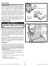
Controller Access
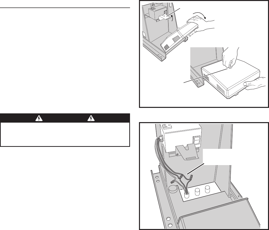
The Controller in models SWR, SWC and SWD is hinged for
access and can be removed without taking off the operator’s
cover. It swings down for installation, programming,
and troubleshooting access (see Figure 8). Under most
circumstances you will not need to remove the Controller.
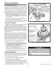
To access the Controller, lift the metal tab below the AC
power switch and swing the Controller down. The Controller
is protected by a plastic dust cover. To remove the dust
cover, loosen the cover’s wing-screw and lift the cover off.
To remove the Controller from the operator, slide the
assembly to the right until the hinges release. Once freed,
you can turn the Controller slightly and remove it from the
operator. Be careful not to pull on the cables too hard.
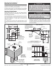
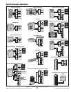
AC Power Connection
All Linear gate operators are supplied with a power disconnect
switch to turn on and off the power available to the operator
(see Figure 9). Following wiring specifi cations on Page 2,
incoming power should be brought into the operator and
connected to the labeled pigtails from the disconnect box. A
wiring connections print can be found on the label inside the
cover of the operator.
Proper thermal protection is supplied with the operator. The
motor contains a thermal overload protector to guard from
overheating the motor due to overload or high-frequency
operation. This overload protector will reset automatically
after the motor cools down.
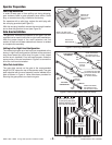
Earth Ground
Install a ground rod and connect it to the operator’s frame
in every gate operator installation. A good earth ground is
necessary to allow the Controller’s built-in surge and lightning
protection circuitry to work effectively. The physical bolting
of the operator to the mounting pad is not suffi cient for
a good earth ground.
✓ NOTE: Do not splice the ground wire. Use a single piece of solid
copper 12 AWG wire between the ground rod and the operator.
1. Install an 8-foot long copper ground rod next to the operator mounting
pad within three feet of the operator.
2. Use a clamp to connect a solid copper 12 AWG ground wire to the
ground rod.
3. Route the ground wire to the operator.
4. Connect the ground wire to the operator’s frame.
LIFT UP ON TAB
CONTROLLER SWINGS DOWN
UNSCREW KNOB
TO REMOVE
CONTROLLER
COVER
Figure 8. Controller Access
Figure 9. Power Disconnect Box Wiring
CONNECT AC POWER
PIGTAIL LEADS TO
THE AC SOURCE
115 VAC WIRING
GREEN - GROUND
BLACK - HOT
WHITE - NEUTRAL
230 VAC WIRING
GREEN - GROUND
BLACK - LINE 1
BLACK - LINE 2
WARNING
ALL AC ELECTRICAL CONNECTIONS TO THE POWER SOURCE AND
THE OPERATOR MUST BE MADE BY A LICENSED ELECTRICIAN
AND MUST OBSERVE ALL NATIONAL AND LOCAL ELECTRICAL
CODES