


SWR • SWC • SWD Swing Gate Operator Installation Guide - 4 - 227965 Revision X13 3-28-2008
Operator Preparation
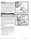
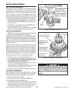
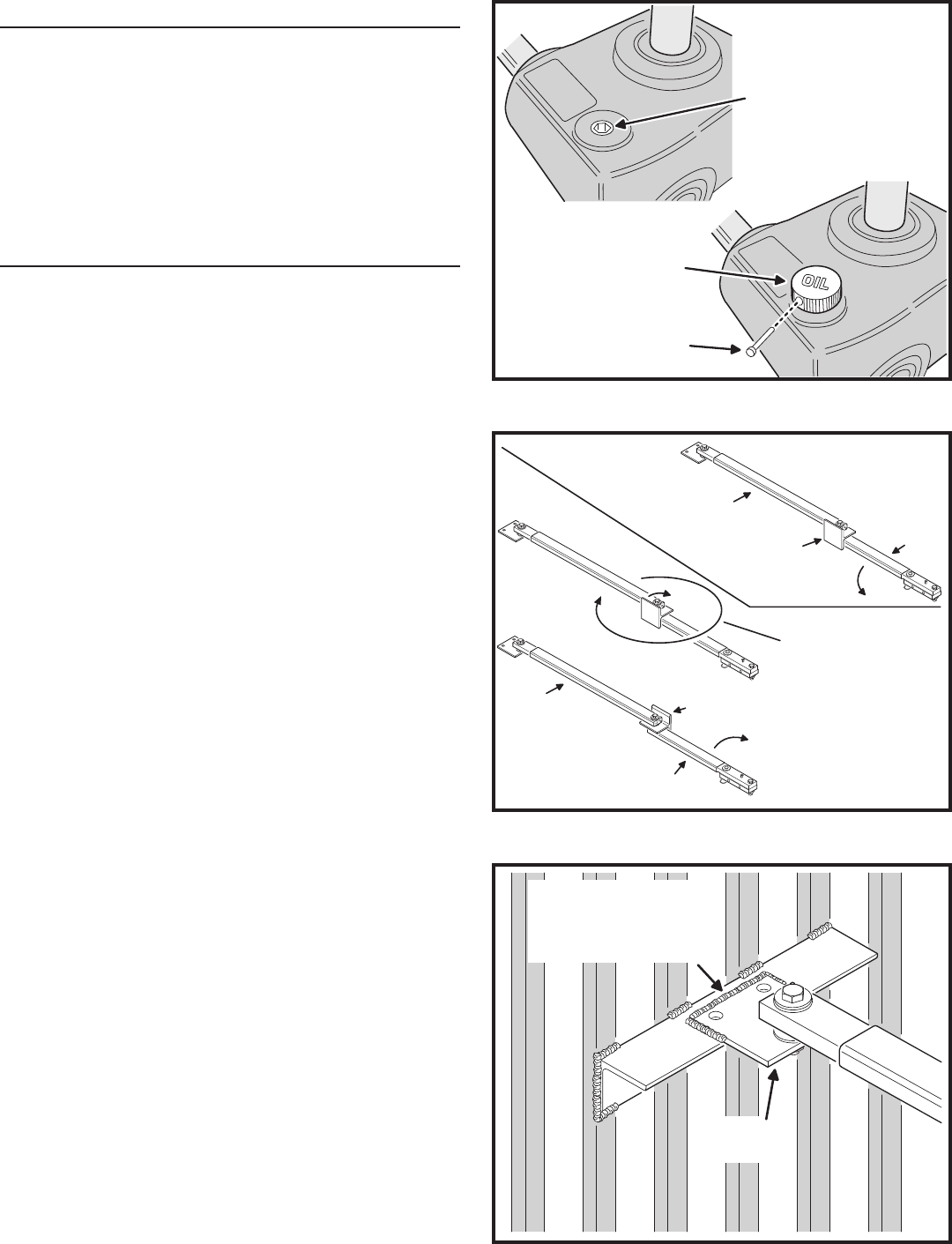
Vent Plug Installation
In order to keep gear oil from spilling out during shipping,
gear reducers used in gate operators have either a solid
plug, or a sealed vent plug, installed at the factory.
For operators with a solid plug, replace the solid plug with
the vent plug provided (see Figure 2).
With the vent plug installed, remove the vent plug’s breather
pin to allow the gear box to vent (see Figure 2).
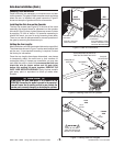
Gate Arm Installation
The gate arm connects the operator to the gate. The arm
supplied can be used in left-hand or right-hand installations.
After the proper length of the crank extension and link
section of the arm has been determined, the arm is welded
to complete the assembly.
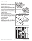
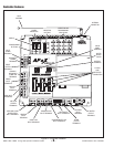
Setting Left or Right Hand Confi guration
The welded style gate arm has been pre-assembled at the
factory in right-hand confi guration (the back of the overtravel
stop faces toward the drive when the gate is fully closed
and the arm is installed). For a left-hand operator, rotate the
upper portion of the arm as shown in Figure 3 to convert the
arm into a left-hand orientation.
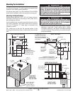
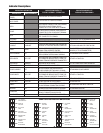
Gate Plate Installation
The gate plate mounts on the gate at the recommended
height (24-7/8” above the top of the operator pad). The gate
plate supplied with the arm assembly can be welded to the
gate as shown in Figure 4. Holes have been provided for
securing the gate plate to an aluminum gate.
REMOVE THE
SOLID PLUG
WITH AN ALLEN
WRENCH
INSTALL THE VENT PLUG
(IF NOT ALREADY INSTALLED)
REMOVE THE
BREATHER PIN
GEAR
REDUCER
Figure 2. Vent Plug Installation
Figure 3. Left or Right Hand Gate Arm Setup
LEFT-HAND
CONFIGURATION
OVERTRAVEL
STOP ON
THIS SIDE
RIGHT-HAND
CONFIGURATION
(AS SHIPPED)
OVERTRAVEL
STOP ON
THIS SIDE
TO CHANGE THE GATE ARM,
ROTATE THE LINK END AND
OVERTRAVEL STOP
ALL THE WAY AROUND
VIEWED FROM INSIDE,
THE OPERATOR IS ON
THE LEFT SIDE OF GATE
VIEWED FROM INSIDE,
THE OPERATOR IS ON
THE RIGHT SIDE OF GATE
LINK
ARM
CRANK
ARM
LINK
ARM
CRANK
ARM
OPEN
OPEN
WELD THE GATE PLATE
TO THE GATE (AN EXTRA
SUPPORT WELDED TO THE
GATE MAY BE REQUIRED)
GATE PLATE
LINK ASSEMBLY
Figure 4. Gate Plate Installation