


MODEL BGUS/BGUS-D • SG/SG-D OPERATOR INSTALLATION GUIDE
-23-
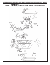
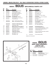
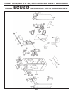
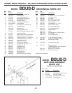
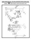
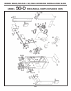
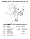
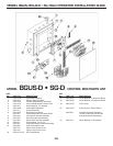
MODEL SG MECHANICAL PARTS LIST
Ref. Part
No. Number Description
1 2110-780* Welded Cabinet Assembly
2 2110-318* Enclosure Door
5 2220-008 Lock Assembly with Key
6 2110-746 Bearing Block Assembly Kit
7 2110-034 Drive Shaft Assembly
8 2110-732 Gate Arm Flange
9 2100-1925-BT Arm Attachment Channel
10 2100-1926-BT Counterweight
2110-441 Connecting Link with Bearings
26 2200-136 Flange Bearings only
17 2500-2090 Motor, 1/2HP, 115VAC
2500-2091 Motor, 1/2HP, 230VAC
18 2100-364 Intermediate Shaft
19 2110-117 Reducer and Crank Arm Assembly
21 2200-917 Reducer Double Pulley, 7”
22 2200-918 Intermediate Pulley, 2” (2 required)
23 2200-151 V-Belt, 25” (2 required)
24 2200-235 Motor Pulley, 1 5/8”
25 2200-011 Pulley, 6” (2 required)
28 2200-208 V-Belt, 26” (2 required)
33 2200-314 Set Collar, 1 1/4”
34 2400-474 Roll Pin, 3/8” x 2”
38 2500-764 Limit Switch
43 2300-028 Limit Cam
50 2400-238 Key, 3/16” x 3/16” x 1 1/4”
60 2200-222 Pillow Block Bearing
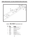
2510-064 Three-Button Station with Lead Wires
2500-033 Standard Three-Button Station only
71 2100-1804 Rear Accessory Shelf
72 2100-1879 Power Box Mounting Plate
73 2510-251-C Power On/Off Disconnect Box, 115VAC
2500-1956 Duplex Receptacles only, 115VAC
2500-1957 Switch only, 115VAC
2510-252-F Power On/Off Disconnect Assembly
on 230VAC Models
2500-2205 Switch only, 230VAC
74 2100-1820 Front Accessory Shelf
* Specify color and texture