


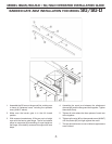
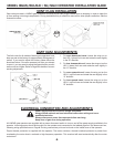
MODEL BGUS/BGUS-D • SG/SG-D OPERATOR INSTALLATION GUIDE
-11-
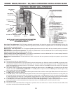
CURRENT SENSING ADJUSTMENTS
Because gates vary in construction and may have different force requirements in the open and close directions to move, the
LINEAR control board has separate Multi-turn potentiometers for adjusting in both directions independently. The adjustment
should be set light enough to maintain minimal force (40 lbs.) should an obstruction occur, but high enough to keep the gate
moving under normal conditions without interruption.
Prior to adjusting the operator current sensing functions, make sure the gate moves freely in both directions. A badly aligned
or poorly maintained gate may cause false triggering of the current sensor. Refer to Page 9 when following the instructions
below. A factory adjustment tool has been supplied to make these adjustments easier. This tool has been taped to the control
box for your convenience.
CLOSE DIRECTION CURRENT SENSE ADJUSTMENT
When the gate operator leaves the factory, it has been preset for a relatively light gate function and will require additional
adjustment. Begin by starting the gate going closed. If the operator stops and reverses, turn the close direction potentiometer
(see Page 9) one turn higher, press the STOP button, and try again. Repeat this process until the gate no longer causes
false tripping of the current sensor. Note that each time the gate operator reverses, the STOP button must be pressed. Next,
turn the close direction potentiometer lower slowly while the operator is running the gate closed until the gate operator stops
and reverses again. From this point, turn the close direction potentiometer higher by 1 1/2 turns for all 115 Volt AC and 24
Volt DC operators, and by 3/4 of a turn higher for all 230 Volt AC operators. Additional fi ne adjustment by 1/4 turns may be
necessary to eliminate false triggering.
OPEN DIRECTION CURRENT SENSE ADJUSTMENT
Repeat the same process with the open direction potentiometer while running the gate in the open direction. Once this is
done, run the gate through several complete cycles and make sure the gate does not false trip in either direction.
MAXIMUM RUN TIMER ADJUSTMENT
This adjustment is not used in barrier gate operators and should be turned fully clockwise.
AUTO CLOSE TIMER ADJUSTMENT
This adjustable potentiometer sets the length of time which elapses before the gate operator automatically closes the gate,
from the fully open position, provided no open, reversing, or obstruction signals are present. This feature can be turned on
or off via dip switch selection. See Page 9 for details. Do not use the auto close timer without an appropriate reversing
device installed!
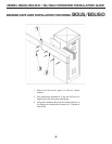
MASTER/SLAVE CONNECTION
A three-wire shielded conductor cable is required to connect master and slave operators. You must use Belden 8760 Twisted
Pair Shielded Cable (or equivalent) only – LINEAR part number 2500-1982, per foot). See Page 9 for details of this connection,
as well as dip switch selection. Note: The SHIELD wire should be connected in both the master and slave operators. In
addition, you must run power to both the master and slave operators.
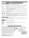
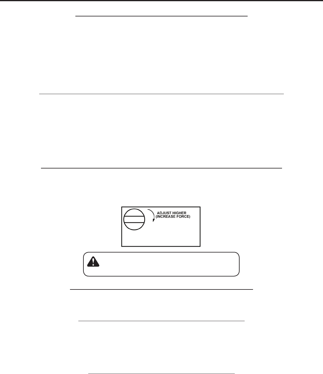
Multi-turn Potentiometer
Remember it is important not to set the adjustment
too high! Doing so will defeat the purpose of the cur-
rent sensing as an obstruction detecting feature.