


MODEL BGUS/BGUS-D • SG/SG-D OPERATOR INSTALLATION GUIDE
-12-
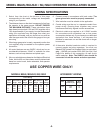
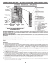
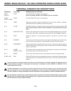
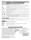
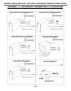
ONBOARD L.E.D. INDICATOR DESCRIPTIONS
Control Board L.E.D. Indicators:
OPEN This indicator is lit when an open signal is present. This signal can come from such devices as button
stations, radio receivers, keypads and telephone entry systems.
CLOSE This indicator is lit when a closed signal is present. This signal typically comes from three-button stations.
STOP This indicator is lit when there is a break in the stop circuit. Make sure there is a stop button wired in and
working properly.
SINGLE This indicator is lit when a signal from a single-button station or radio receiver is present.
CLOSE OBST This indicator is lit when an open/reset signal is present. This signal can come from loop detector or other
switch wired to oepn/reset input terminal #50.
OPEN OBST This indicator is lit when an open/reset signal is present. This signal can come from a loop detector or
switch connected to terminal #50.
REVERSING This indicator is lit when a reversing signal is present. This signal is generated by a loop detector wired
to the safety loop terminals.
SHADOW LOOP This indicator is lit when a reset signal is present. This signal is generated by a loop detector wired to the
reset loop terminal #11.
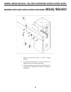
These indicators are lit when the open #1 limit switch is activated on a right-hand operator, or the close
#1 switch on a left-hand. If this indicator is lit and the gate is not in its full open/closed position, the limit
may need adjusting or the limit switch may need replacing.
These indicators are lit when the close #1 limit switch is activated on a right-hand operator, or the open
#1 on a left-hand. If this indicator is lit and the gate is not in its full open/closed position, the limit may
need adjusting or the limit switch may need replacing.
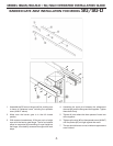
Motor Board L.E.D. Indicators:
NON LABELED One of these two indicators will be lit when the motor is running the gate open, and the other is lit when
the motor is running the gate closed.
BRAKE REL. This indicator is lit when the motor is running in either direction. This function is not used on this operator.
DC Operators Only:
AC POWER Indicates AC power is supplying the unit.
DC POWER Indicates the operator is running on batteries.
BATTERY
CHARGING Indicates batteries are being charged. Light goes out when batteries reach 90% of full charge.
OPEN GATE Operator is in open then lockout stage.
POWER
LOCKOUT Flashes when controls/motor are in lockout mode.
LH
RH
LSC-1
LSC-2
LSO-1
LSO-2
LSO-1
LSO-2
LSC-1
LSC-2
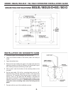
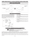
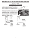
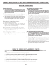
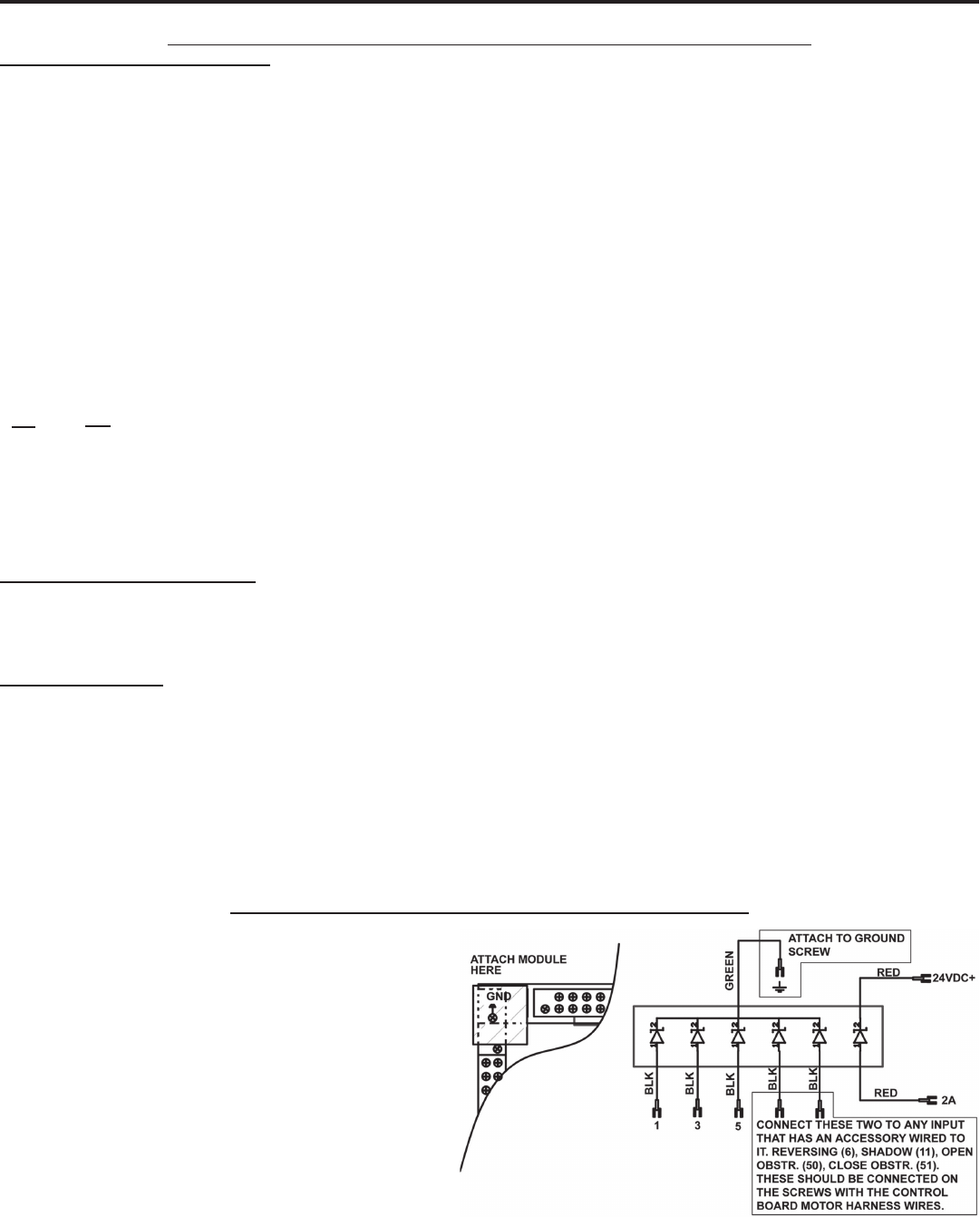
SURGE PROTECTOR INSTRUCTIONS
The optional surge protector should be connected to
any inputs that have an accessory connected to it. This
includes the 3-button station, so it must be connected
to 1, 2A and 3 in all cases. The green wire connected to
ground, which is electrically the same as terminal 4. The
red wires connect to terminals 2A and 24VDC+. This
will cause the 2 amp fuse to blow if this section of the
module becomes shorted. With any of the other inputs
connected to the surge protector, if their protection line
becomes shorted due to a surge over the rating of the
module, the corresponding LED on the main board will
remain lit, causing a constant signal to the controller. If
this is found, please replace the entire surge protector
with a new unit.
Do not simply unhook the shorted wire, as this
removes the protection from the circuit that was saved
by the protector in the fi rst place!