


Installing and Replacing Desktop Board Components
45
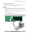
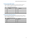
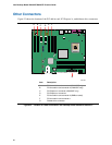
Connecting Hi-Speed USB 2.0 Headers
Before connecting the USB 2.0 headers, observe the precautions in "Before You Begin" on
page
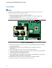
27. See Figure 21, D on page 43 for the location of the black USB 2.0 headers.
Table 11 shows the pin assignments for the headers.
Table 11. Hi-Speed USB 2.0 Header Signal Names
USB Port A USB Port B
Pin Signal name Pin Signal name
1 Power 2 Power
3 D- 4 D-
5 D+ 6 D+
7 Ground 8 Ground
9 Key 10 No connect
Note: USB ports may be assigned as needed.
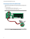
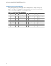
Connecting IEEE 1394a Headers (Optional)
Before connecting the IEEE 1394a headers, observe the precautions in "Before You Begin" on
page
27. See Figure 21, E on page 43 for the location of the blue IEEE 1394a headers. Table 12
shows the pin assignments for the headers.
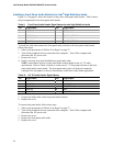
Table 12. IEEE 1394a Header Signal Names
Pin Signal Name Pin Signal Name
1 TPA1+ 2 TPA1-
3 Ground 4 Ground
5 TPA2+ 6 TPA2-
7 +12 V 8 +12 V
9 Key (no pin) 10 Ground