


Intel Desktop Board D945GNT/D945GTP Product Guide
44
Installing a Front Panel Audio Solution for Intel
®
High Definition Audio
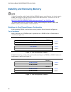
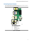
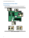
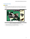
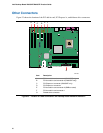
Figure 21, F on page 43 shows the location of the yellow front panel audio header. Table 9 shows
the pin assignments for the front panel audio header.
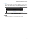
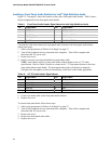
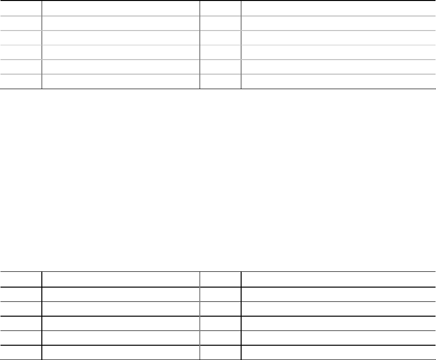
Table 9. Front Panel Audio Header Signal Names for Intel High Definition Audio
Pin Signal Name Pin Signal Name
1 PORT 1L 2 GND
3 PORT 1R 4 PRESENCE#
5 PORT 2R 6 SENSE1_RETURN
7 SENSE_SEND 8 KEY (no pin)
9 PORT 2L 10 SENSE2_RETURN
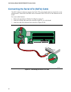
To install the cable that connects the front panel audio solution to the front panel audio header,
follow these steps:
1. Observe the precautions in "
Before You Begin" on page 27.
2. Turn off all peripheral devices connected to the computer. Turn off the computer and
disconnect the AC power cord.
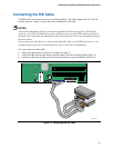
3. Remove the cover.
4. Install a correctly keyed and shielded front panel audio cable.
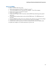
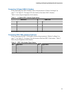
NOTE: some chassis still use a front panel audio solution based on the AC ’97 audio
specification. Refer to Table 10 below to connect an AC ’97 front panel solution to the front
panel audio header on the board. The front panel audio jacks will need to be manually
configured for microphone or line out functionality in the Intel Audio Studio application.
Table 10. AC ’97 Audio Header Signal Names
Pin Signal Name Pin Signal Name
1 MIC 2 AUD_GND
3 MIC_BIAS 4 AUD_GND
5 FP_OUT_R 6 FP_RETURN_R
7 AUD_5V 8 KEY
9 FP_OUT_L 10 FP_RETURN_L
5. Connect the audio cable to the front panel audio solution.
6. Replace the cover.
To restore back panel audio, follow these steps:
1. Observe the precautions in "
Before You Begin" on page 27.
2. Turn off all peripheral devices connected to the computer. Turn off the computer and
disconnect the AC power cord.
3. Remove the cover.
4. Remove the front panel audio cable.
5. Replace the cover.