


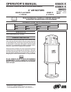
PAGE 7 OF 86564XĆX
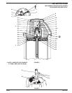
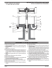
FIGURE 8
36 WASHER GROOVE
40 EXTENSION ROD
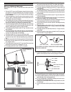
32. Pull the (42) piston adapter up around the (36) washer.
33. Place the (16) washer over the (40) extension rod and into the (42)
piston adapter.
34. Clean with solvent and put Loctite 271 on the threads of the (31)
valve piston. Screw the (31) valve piston into the (42) piston adapter
and tighten (see figure 3).
35. Push the assembled (42) piston adapter and (31) valve piston down
thru the 90350 installation tool until they bottom.
36. Remove the 90350 installation tool.
37. Install the (37) upper gland over the (31) valve piston and push
down, being careful to retain the (38) seal in the O" ring groove.
38. Align the two bolt holes and secure the (37) upper gland to the (18)
head assembly with the two (6) machine screws and two (7) lock
washers (see figure 9).
39. Insert the (12) insert spring assembly in the (18) head assembly,
with the hooks down and the nylon roller toward the (31) valve piston
(see figures 2 and 9).
40. Thoroughly grease and insert the (34) pilot insert, two (35) valve
guides, (33) valve plate and (32) gasket into the (18) head assembly
(see figure 9).
41. Thoroughly grease and insert the (13) valve insert into the (18) head
assembly (see figure 2).
42. Thoroughly grease and insert the (14) gasket and the (11) valve
plate and pin assembly between the (13) valve insert and the (18)
head assembly, with the two pins in the (11) valve plate and pin asĆ
sembly up (see figures 2 and 9).
43. Hook the round coils in the (12) insert spring assembly over the pins
in the (11) valve plate and pin assembly (see figure 9).
44. Hook the bottoms of the (12) insert spring assembly into the holes on
the side of the (11) valve plate and pin assembly.
45. Insert the (9) valve guide against the face of the (11) valve plate and
pin assembly. The legs of the (9) valve guide should be down, with
the leg having the threaded hole the farthest from the bottom toward
the air inlet in the (18) head assembly.
46. Insert and tighten across corners of eight (4) machine screws and
eight (5) washers (see figures 1 and 9).
47. Thoroughly grease and install the (10) gasket in the (8) air motor
cap.
48. Place the (8) air motor cap on the (18) head assembly and secure
with the six (3) screws (see figure 2).
49. Place the (2) deflector on exhaust port of the (18) head assembly,
with the opening down, and secure with four (1) machine screws
(see figure 2).
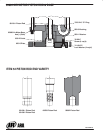
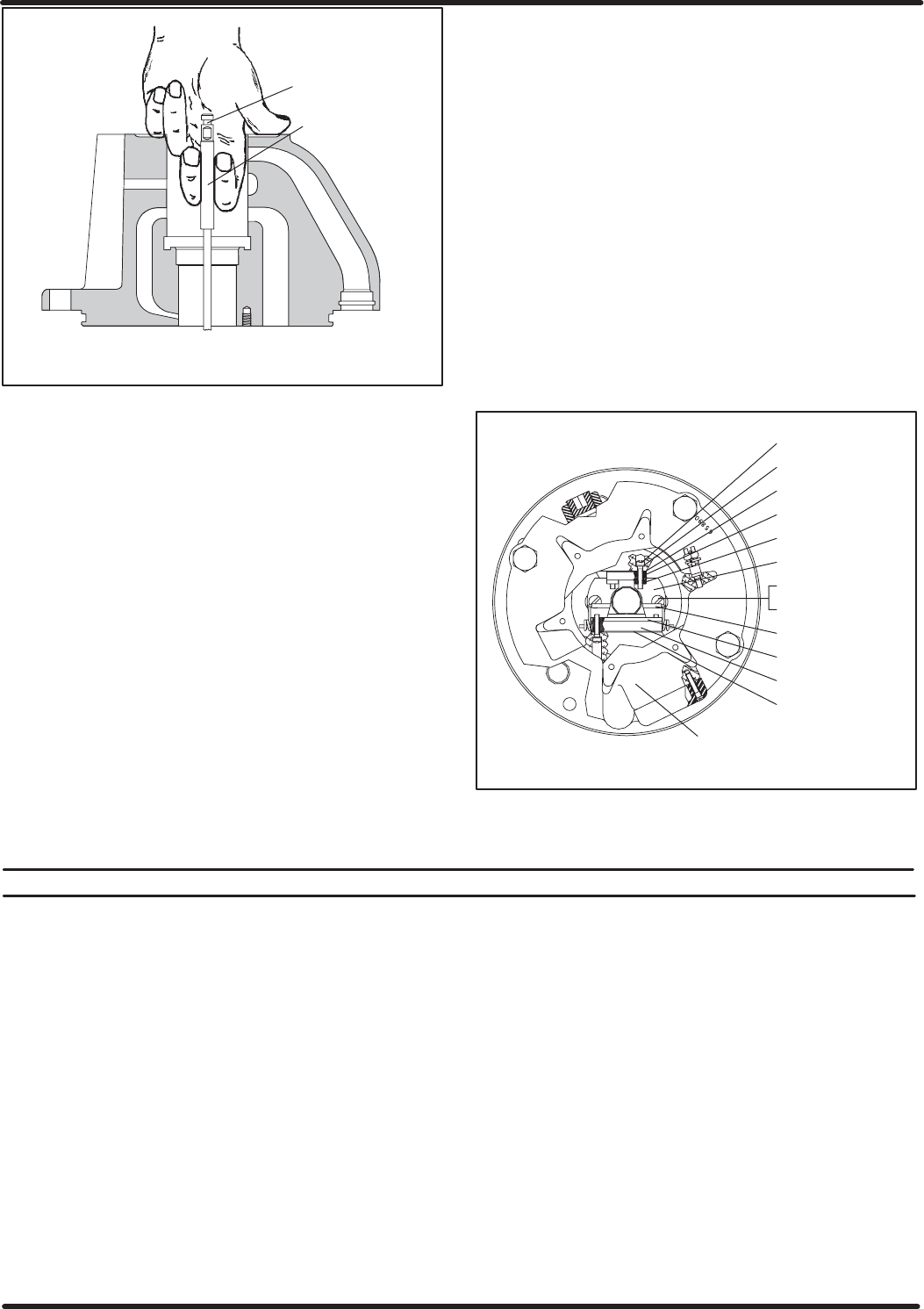
FIGURE 9
32 GASKET
33 VALVE PLATE
35 VALVE GUIDE (2)
37 UPPER GLAND
6 SCREW (2)
7 LOCK WASHER (2)
12 SPRING ASS'Y
9 VALVE GUIDE
11 VALVE PLATE
14 GASKET
18 HEAD ASSEMBLY
5 WASHER (8)
4 SCREW (8)
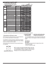
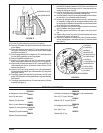
TROUBLE SHOOTING
PROBLEM
Air leakage out of main exhaust.
CAUSE
Worn (13) valve insert.
REMEDY
Replace (13) valve insert.
CAUSE
Worn (11) valve plate and pin assembly.
REMEDY
Replace (11) valve plate and pin assembly.
CAUSE
Damaged (23) piston assembly.
REMEDY
Replace (23) piston assembly.
PROBLEM
Continual air leakage out of bleeder hole in (18) head assembly.
CAUSE
Worn (15) O" ring or (38) seal.
REMEDY
Replace (15) O" ring and (38) seal.
PROBLEM
Air leakage around (52) piston rod.
CAUSE
Worn (49) U" cup.
REMEDY
Replace (49) U" cup.