


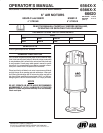

PAGE 6 OF 8 6564XĆX
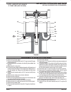
REASSEMBLY OF AIR MOTOR
NOTE: ALL THREADS ARE RIGHT HAND.
Apply grease to all O" rings, U" cups and other rubber goods when
installing.
1. Slip the (24) O" ring on the (22) adapter, clean with solvent and apĆ
ply Loctite 271 to the external threads of the (22) adapter. Assemble
the (22) adapter and (25) nut to the (23) piston assembly and tighten
to 160 Ć 180 ft lbs.
2. Put the threaded end of the (26) valve rod thru the hole in the (22)
adapter, with the machined shoulder" end of the (26) valve rod on
the threaded side of the (22) adapter.
3. While holding the (26) valve rod below the threads with locking pliĆ
ers, clean with solvent and apply Loctite 271 to the threads and atĆ
tach the (40) extension rod, using the provided wrench flats.
4. Place the machined shoulder" end of the (26) valve rod into the hole
in the end of the (52) piston rod and assemble (52) piston rod to (22)
adapter, tightening using a wrench on flats provided.
5. Thoroughly grease and install the (20) O" ring in the (30) air motor
base assembly.
6. Grease and place the (51) washer and (49) U" cup into the (30) air
motor base assembly. Place the (48) guide washer and (47) retainĆ
ing ring in the (30) air motor base assembly.
7. Grease and install (15) O" ring on the (43) lower gland.
8. Grease the bore in the (18) head assembly and insert the (43) lower
gland into the bore of the (18) head assembly, using a twisting moĆ
tion.
9. Align the screw holes in the (43) lower gland and (18) head assembly.
10. Secure the (43) lower gland to the (18) head assembly using four
(21) machine screws.
11. Put the (52) piston rod thru the (49) U" cup in the (30) air motor base
assembly, being careful not to damage the U" cup.
12. Thoroughly grease the inside of the (27) air cylinder.
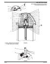
FIGURE 5
27 CYLINDER (APPLY
GREASE THROUGHOUT
INSIDE)
52 PISTON ROD
23 PISTON
(APPLY GREASE
AROUND EDGE)
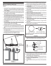
13. Fill the area between the lips of (23) piston assembly with grease,
then insert into the bottom of the (27) air cylinder (see figure 3).
14. Push the (23) piston assembly to the top of the (27) air cylinder.
15. Thoroughly grease and install the (45 and 20) O" rings into the (18)
head assembly.
16. Thoroughly grease the two (17) O" rings and install one in the (30)
air motor base assembly. Install the other in the (18) head assembly.
17. Press the (28) tube into the counterbored hole in the (30) air motor
base assembly.
18. Push the (40) extension rod thru the (45) O" ring in the base of the
(18) head assembly.
19. Press the (18) head assembly down until the (27) air cylinder and
(28) tube are seated in the (18) head assembly.
20. Insert the four (46) bolts down thru the holes in the flanges of the (18)
head assembly and the (30) air motor base assembly.
21. Screw the four (50) nuts on the four (46) bolts. Alternately and evenly
tighten the nuts.
22. Thoroughly grease and install the (19) U" cup in the (42) piston
adapter, with the lips of the (19) U" cup down toward the thick flange
on the (42) piston adapter.
23. Thoroughly grease and install the (39 and 15) O" rings in the (37)
upper gland.
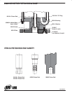
24. Bend the (38) seal in a heart shape and install in the (37) upper gland
inside the (39) O" ring (see figure 6).
FIGURE 6
SEAL FREE FORM SEAL COLLAPSED FORM
PUSH SIDES IN, AS SHOWN, THEN SLIDE INTO BORE AND POSIĆ
TION SEAL IN GROOVE.
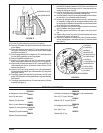
25. Grease and carefully push the (31) valve piston into the (37) upper
gland to size the (38) seal, then remove (see figure 7 below).
FIGURE 7
38 SEAL
39 ``O" RING
15 ``O" RING
37 UPPER GLAND
31 VALVE PISTON
DIRECTION FOR SIZING
26. Place the (44) washer over the (40) extension rod.
27. Pull the (40) extension rod up and grasp with two fingers (see figure 8).
28. Place the 90350 installation tool over the (40) extension rod, with the
turned diameter down and the chamfer up.
29. Fit the turned diameter of the 90350 installation tool into the bore in
the bottom of the (18) head assembly.
30. Place the (42) piston adapter down over the (40) extension rod, with
the threads up.
31. Insert the (36) washer into the groove in the top of the (40) extension
rod.