


- 40 -
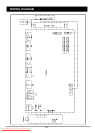
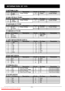
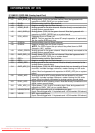
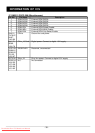
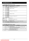
IC SAA5264PS/M3/0104 SDIP52
Pin No. Pin Name Description
37 VSYNC Vertical sync pulse input; Schmitt triggered for a TTL version; the
polarity of this pulse is programmable by register bit TXT1. V POLARITY
38 VSSP Periphery ground
39 VDDC Core supply voltage (+3.3V)
40 OSCGND Crystal oscillator ground
41 XTALIN 12 MHz crystal oscillator input
42 STALOUT 12 MHz crystal oscillator output
43 RESET Reset input; if this pin is HIGH for at least 2 machine cycles (24 oscillator
periods) while the oscillator is running, the device resets; this pin
should be connected to VDDP via a capacitor
44 VDDP Periphery supply voltage (+3.3V)
45 Input/output for general use
46 Input/output for general use
47 Input/output for general use
48 Input/output for general use
49 SCL I
2
C-bus Serial Clock input from application
50 SDA I
2
C-bus Serial Data input/output (application)
51 Input/output for general use
52 Input/output for general use
INFORMATION OF ICS
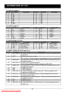
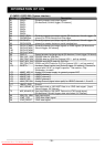
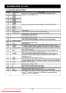
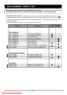
IC TPA1517NE DIP20
Pin No. Pin Name Description
1 IN1 IN1 is the audio input for channel 1.
2 SGND SGND is the input signal ground reference.
3 SVRR SVRR is the midrail bypass.
4 OUT1 OUT1 is the audio output for channel1.
5 PGND PGND is the power ground reference.
6 OUT2 OUT2 is the audio output for channel 2.
7 VCC VCC is the supply voltage input.
8 M/SB M/SB is the mute/standby mode enable. When held at less than 2 V,
this signal enables the TPA1517 for standby operation. When held
between 3.5V and 8.2V,this signal enables the TPA1517 for mute
operation. When held above 9.3V, the TPA1517 operates normally.
9 IN2 IN2 in the audio input for channel 2.
10-20 GND/HS GND/HS are the ground and heatsink connections. All GND/HS
terminals are connected directly to the mount pad for thermal-enhanced
operation.
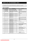
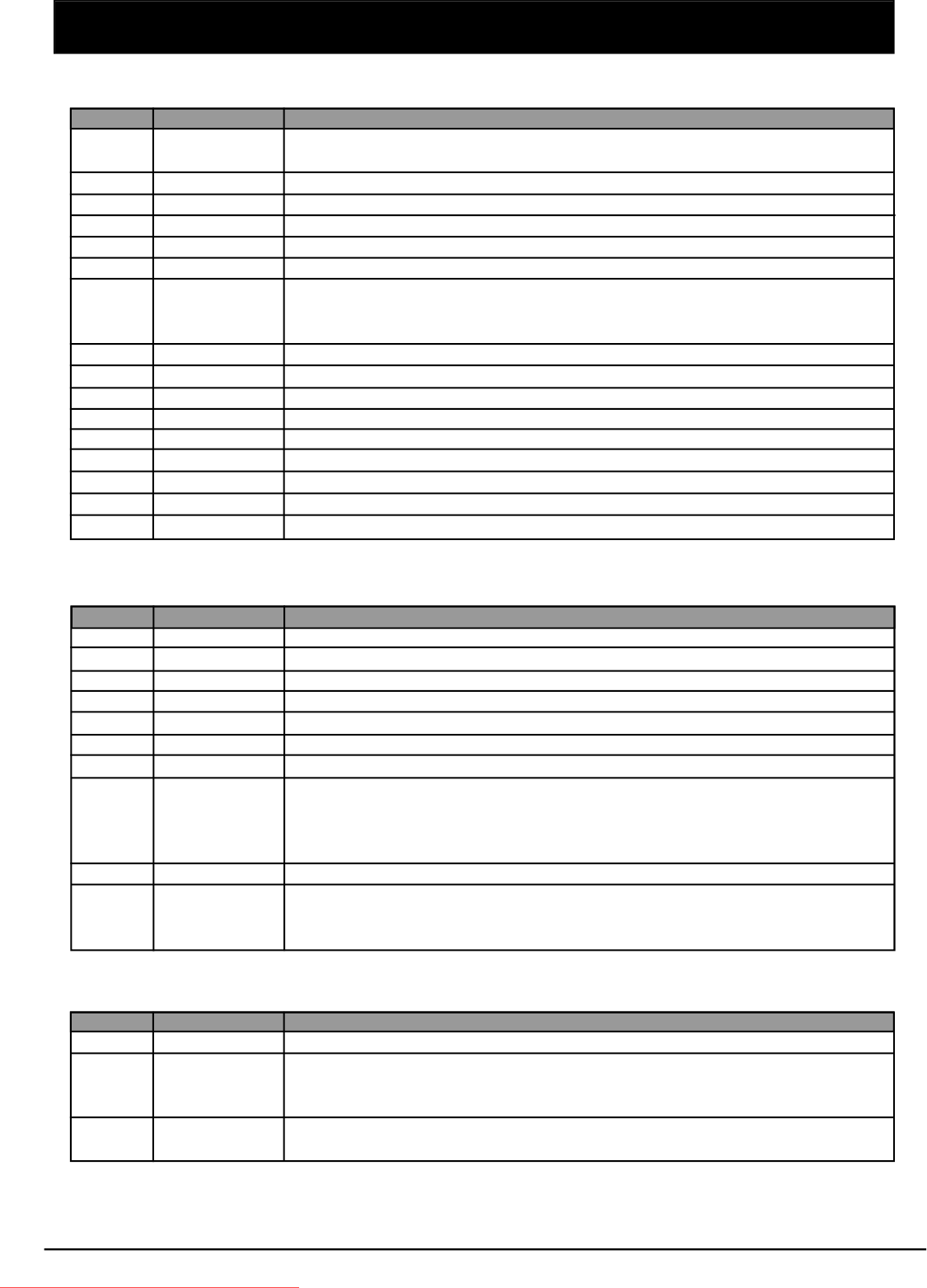
IC TVP5146PFP S-PQFP-G80 (Clock Signals)
Pin No. Pin Name Description
40 DATACLK Line-locked data output clock.
74 XTAL1 External clock reference input. it may be connected to an external
oscillator with a 1.8V compatible clock signal or a 14.31818-MHz
crystal oscillator.
75 XTAL2 External clock reference output. Not connected if XTAL1 is driven by an
external single-ended oscillator.
Downloaded From TV-Manual.com Manuals