


9
Level
Installation, operation & maintenance instructions
IP152, Rev AD
April
2012
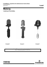
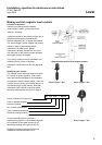
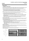
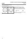
Switching Point Adjustment
Each switch mechanism is mounted on a
bracket, which is secured on the pressure
tube by a locking screw and lock nut.
These can be loosened, allowing the bracket
to be adjusted up or down as required. Always
ensure that the small pressure plate between
the locking screw and pressure tube is in
place before re-tightening the locking screw
nut.
Important note: Switches can not be
adjusted outside of the range set by the stops
on the pressure tube. Displacer operation
controls are covered in Installation Instruction
booklet IP153
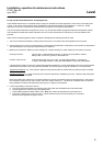
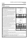
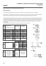
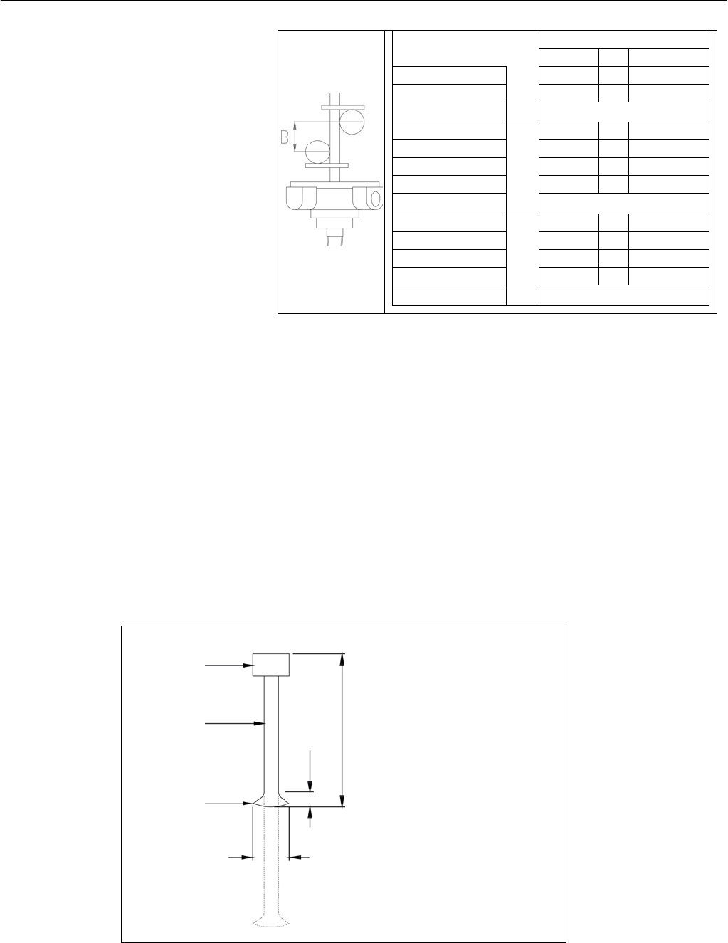
Float Rod Length Adjustment
The highest operating level given by the float rod as supplied can be made higher (i.e. nearer the mounting point) by shortening
the float rod on site, as follows:
Remove float unit from control by locating the Stop Assembly in the base of the 1”NPT threaded boss and easing the spring clip
out of the two locating holes in the pressure tube. The rod and the magnet assembly can now be withdrawn from the pressure
tube. Undo the hexagonal float adaptor to remove the float from the rod, and slide the adaptor up the rod. Hacksaw the stainless
steel rod to the required length according to the diagram below, and then re-clench the rod end in a vice as shown. Re-fit the
float, ensuring the spring washer is used between float and adaptor.
Re-fit the float unit to the switch head, ensuring that the magnet is free from swarf and debris. Locate the two ends of the spring
clip in the two cross holes in the pressure tube; ensuring that the rod and magnet assembly are free to move vertically in the
pressure tube and that it is securely retained by the Stop Assembly.
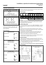
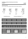
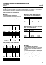
Enclosure type
R7A
R7I
R4N
Switch Mechanism Type
D4, P4, X4 H4 D8, P8, X8, H8
Max. No. Switches 1 1 7
Sw. Adjustment ‘B’ 7 7 7
Max. Wet switching
differential
Type 11F, 12F, 13F, 14F : 20mm
Max. No. Switches
S7A
S7I
S4N
4 4 2
Sw. Adjustment ‘B’ 94 94 94
Max. Sw Crs ‘B’ 94 94 94
Min. Sw Crs ‘B’ 7 0 56
Max. Wet switching
differential
Type 11F, 12F, 13F, 14F : 114mm
Max. No. Switches
L4N
6 6 3
Sw. Adjustment ‘B’ 194 194 194
Max. Sw Crs ‘B’ 194 194 194
Min. Sw Crs ‘B’ 7 0 56
Max. Wet Switching
differential
Type 11F, 12F, 13F, 14F : 214mm
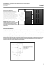
Minimum lengths with switch heads to
give highest operating level of 190mm
R7A R71 R4N : 316
S7A S71 S4N : 421
L4N : 521
Magnet
Rod
Cut &
re
-
clench
3.5 min
3.0 min