


12
Level
Installation, operation & maintenance instructions
IP152, Rev A
D
April 2012
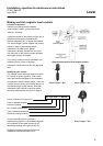
When fitting a spare or replacement switch mechanism
IMPORTANT NOTE
If a spare switch mechanism is fitted at any time, it is important that the magnet system is left in the correct mode.
After installation of a replacement switch mechanism, always check that the B-B contacts are made, assuming the chamber is
empty of liquid. If the chamber is full of liquid, then A-A contacts should be checked to ensure they are made.
If it is found that a switch mechanism is not in the correct mode, then the liquid level in the chamber should be raised such that
the primary float magnet passes through the switching point. Lowering the liquid level will then cause the float magnet to fall
back through the switching point, thus leaving the switch mechanism in the correct operating mode (For a control operating as
low level alarm, the liquid level should be first lowered then raised back to ensure the switch mechanism is in the correct
operating mode).
Full fitting instructions are supplied with each spare or replacement switch mechanism.
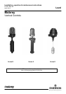
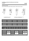
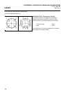
Se
ries B Series X Series D
Complete float
assembly, comprising
float unit and
rod and magnet
assembly
11F
N/A
Sealed
Chamber
Contact factory with
full model number and
complete assembly
can be supplied
12F
13F
14F
17D
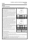
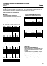
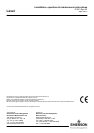
Switch mechanism kit
comprising
Switch mechanism and fittings
Series B,X,D
Weatherproof
Series B,X,D
Weatherproof
4 Contact 5 Amp D4 SK178 SK178
4 Contact plated P4 SK179 SK179
4 Contact 10 Amp X4 SK180 SK180
4 Contact sealed H4 SK181 SK181
8 Contact 5 Amp D8 SK182 SK182
8 Contact plated P8 SK183 SK183
8 Contact 10 Amp X8 SK184 SK184
8 Contact sealed H8 SK185 SK185
Sales Kit SK190 SK191
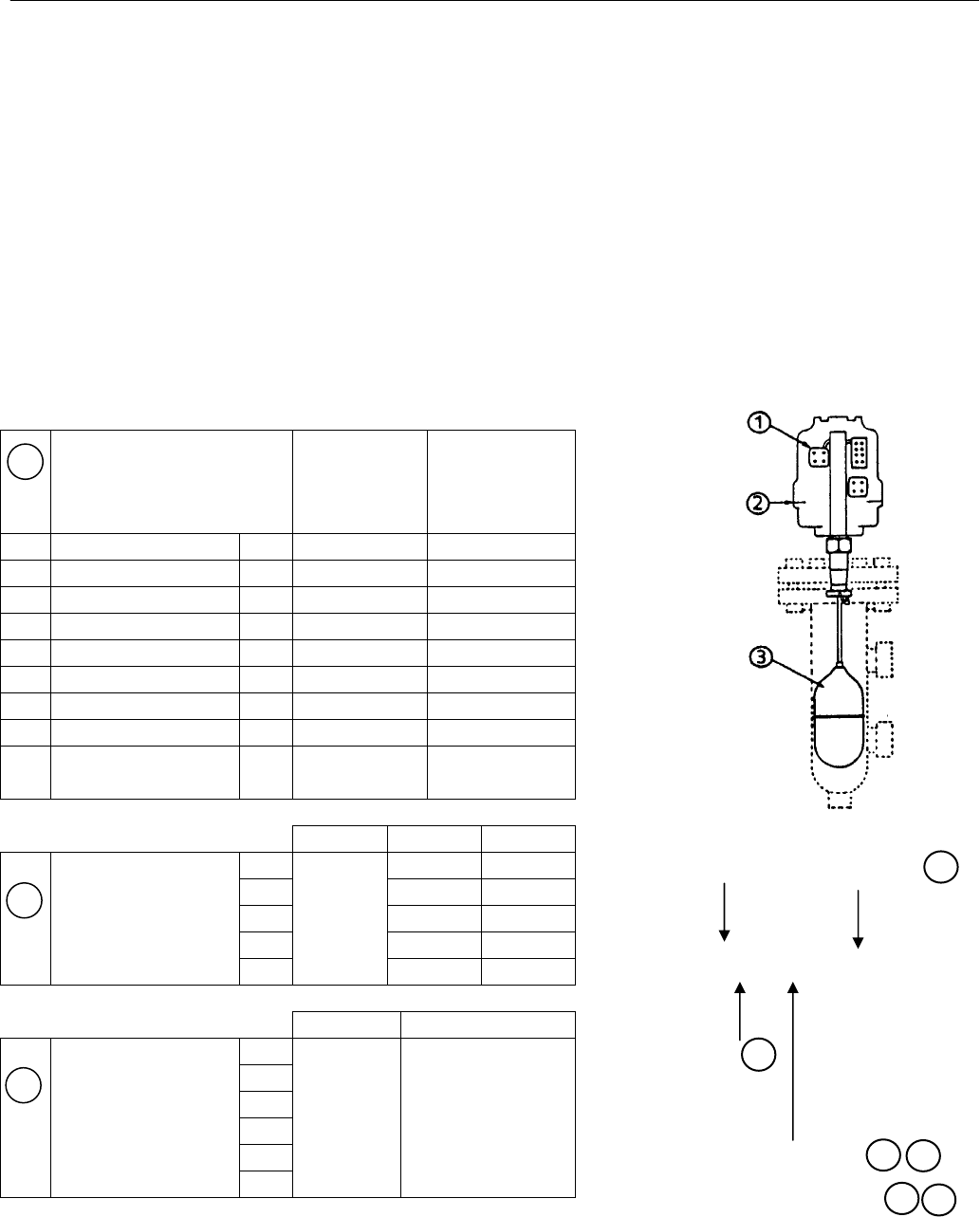
Series B Series X Series D
Float unit only 11F
N/A
Sealed
Chamber
SK192 SK192
12F SK193 SK193
13F SK194 SK194
14F SK195 SK195
17D SK196 SK196
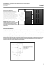
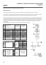
1
1
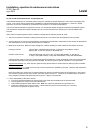
XC13F S7A 1 D8/112
Series
Mechanism
7 = Flameproof
4 = Weatherproof
Float
3
1
1
2
2
1
2