


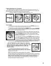
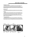

Check attachment of all wheels.
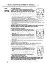
This jogging stroller is equipped with quick release wheel retention mechanisms. The
quick release allows the wheel to be installed and removed without tools. For proper and
safe performance, read and follow these instructions carefully:
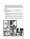
1. Check all wheels of your jogging stroller before every use.
Front wheel
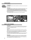
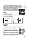
2. For the front wheel, move the quick release lever to the OPEN position and
set the wheel so it firmly touches the inside of the fork ends.
3. With the lever about halfway between the
OPEN position and the CLOSED
position (Fig. 24), tighten the quick release adjusting nut on the opposite end of the
quick release axle until finger-tight (Fig. 25).
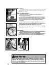
4. Place the quick release lever in the palm of your hand and
move the lever in a motion as shown in Figure 26. Move the lever
into the
CLOSED position (Fig. 28). At the halfway closed
position of the quick release lever, you should start to feel some
resistance to this motion.
5. If the lever is moved to the
CLOSED position with little or
no resistance, clamping strength is insufficient. Simply return the
lever to the
OPEN position, tighten the quick release adjusting
nut further and close the lever, testing again for resistance. When
the quick release device is properly tightened, and clamped to the
closed position, the clamping force is adequate to cause metal
into metal engagement (embossing) of the fork surfaces.
• Do not tighten the quick release by using the
quick release lever like a wing nut (Fig. 27). This
will not result in sufficient force to hold the
wheel in place.
6. Orient the quick release lever so that it does not
interfere with any other stroller part and so that it will not
become accidentally snagged by obstacles in the path of the
jogging stroller (Fig. 28).
Note: If your dropouts don’t appear parallel, this is normal
when the wheel is not inserted and tightened, especially the Cavalier 2. First ensure
that both handlebar height adjustment levers are oriented in the same direction (see
page 12) and the locking tension bar is correctly seated. It may be possible to
slightly correct minor twisting. Use moderate, gradual movements with hands only
(no tools, feet or force) to tweak in the desired direction. The bolted aluminum
construction allows for slight corrections.
Fig. 28
Fig. 29
Push button
Hub Clevis Axle
15
OPEN
CLOSED
OPEN
CLOSED
OPEN
OPEN
OPEN
OPEN
Fig. 24
Fig. 25 Fig. 26
Fig. 27
OPEN
CLOSED