


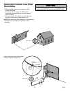

Moving Gate C
an Cause Movi
ng Gate
C
an Cause
Injury or Death I
nj
ury or Death
KEEP CLEAR! K
EE
P C
LEA
R! Gate may move at any G
ate
m
ay move at
any
time witho
ut pri
or warning. ti
m
e wi
tho
ut prior w
arning.
Do n
ot let chi
ld
ren op
erate the gate or D
o n
ot
l
e
t c
hi
l
d
r
e
n ope
rate th
e gate or
play in th
e
gate area. pl
a
y
in
th
e
g
a
t
e
a
rea
.
This entrance is for
vehicles on
ly Th
i
s
e
ntran
c
e
is
fo
r
v
eh
i
c
l
e
s
on
l
y
Pedestrians must use separate en
trance P
e
de
st
ria
ns
mus
t
us
e
s
e
pa
r
a
te
en
tr
a
nc
e
L1
R1
R2
Z1
K5
K6
K2
F3
10A 32V
D1
Ø
P1
Z9
Z8
F2
F6
D4
D2
R9
C64
JMPR1
U4
FORCE
TIMER TO
CLOSE
OFF MAX
FUSE
OPEN
R35
D9
Z3
Z4
U3
D1
D27
F5
C11
C13
C12
D15
C2 R4
R1
Ø
1
R1
ØØ
R9
Ø
Q9
K1
R196
Q22
D8
K3
K4
D21
D22
C4
ACCESSORY
OVLD
D6
JMPR2
MOV1
MOV2
DB1
U2
Z12
24 VAC/
SOLAR
INPUT
GATE 2
ACCESSORY
POWER
MAGLOCK
ALARM
GATE 1
C
C
NC
NO
NO
GRN
WHT
YEL
BLU
RED
BRN
GRN
WHT
YEL
BLU
RED
BRN
F4
10A 32V
F7
24V
TIMER
RUNNING
GATE 2
SET
OPEN
LIMIT
SET
CLOSE
LIMIT
LEARN
LIMITS
DIAGNOSTIC
GATE 1
J4
LEARN
XMITTER
MAGLOCK
ON OFF
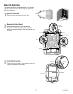
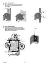
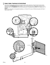
Control Box
18 18
R93 R93
D42 D42
K2 K2
D1D1
Ø Ø
Z22 Z22
P1 P1
F2 F2
MOV1 MOV1
D1 D1
Q12 Q12
U4 U4
D129 D129
Z4 Z4
U3 U3
D2 D2
D44 D44
C11 C11
C13 C13
D16 D16
F9 F9
R1R1
Ø
1 1
R1R1
ØØ ØØ
K1 K1
Q22 Q22
F3 F3
K3 K3
K4 K4
R196 R196
F1 F1
Z12 Z12
GATE 2 GATE 2
GR GR
WH WH
YL YL
BL BL
RD RD
BR BR
F7 F7
24V 24V
GATE 2 GATE 2
SET SET
OPEN OPEN
LIMIT LIMIT
SET SET
CLOSE CLOSE
LIMIT LIMIT
LEARN LEARN
LIMITS LIMITS
GATE 1 GATE 1
C69 C69
J2J2
Ø Ø
D8 D8
D4 D4
R9 R9
R329 R329
R27 R27
MOV2 MOV2
R4 R4
C2 C2
Z1 Z1
R2 R2
K5 K5
F12 F12
Q9 Q9
R9R9
Ø Ø
F8 F8
Q6 Q6
Q1 Q1
C75 C75
C73 C73
C72 C72
C71 C71
C7C7
Ø Ø
C66 C66 C65 C65
C68 C68
C33 C33
F11 F11
R42R42
Ø Ø
R423 R423
J24 J23 3J24 J23 3
Ø
A 32V A 32V
3 3
Ø
A 32V A 32V
J21 J21
30 30
30 30
C64 C64
R22 R22
U2 U2
J18 J18
K6 K6
JU1 JU1
JU2 JU2
DB1 DB1
D36 D36
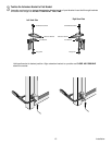
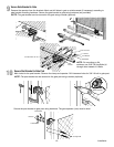
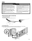
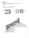
23 Wiring
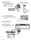
Insert Operator Cable
Insert watertight connector into the bottom of the control box and tighten with nut. Insert operator
cable through watertight connector mounted in the bottom of the control box.
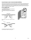
To reduce the risk of SEVERE INJURY or DEATH:
• ANY maintenance to the operator or in the area near the
operator MUST not be performed until disconnecting the
electrical power and locking-out the power via the operator
power switch. Upon completion of maintenance the area
MUST be cleared and secured, at that time the unit may be
returned to service.
• Disconnect power at the fuse box BEFORE proceeding.
Operator MUST be properly grounded and connected in
accordance with local electrical codes. NOTE: The operator
should be on a separate fused line with a 15 amp
circuit breaker.
• ALL electrical connections MUST be made by a qualified
individual.
• DO NOT install ANY wiring or attempt to run the operator
without consulting the wiring diagram. We recommend that
you install an optional reversing edge BEFORE proceeding
with the control station installation.
• ALL power wiring should be on a dedicated circuit and well
protected. The location of the power disconnect should be
visible and clearly labeled.
• ALL power and control wiring MUST be run in separate
conduit.
• BEFORE installing power wiring or control stations be sure to
follow ALL specifications and warnings described below.
Failure to do so may result in SEVERE INJURY to persons
and/or damage to operator.
ATTENTION
AVERTISSEMENT AVERTISSEMENT
AVERTISSEMENT
WARNING
CAUTION
WARNING
WARNING WARNING
PRECAUCIÓN
ADVERTENCIA
ADVERTENCIA ADVERTENCIA
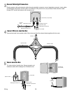
WIRING
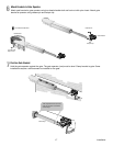
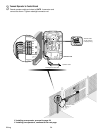
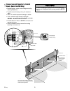
Connect Gate Operator (Gate 1) to Control Box
1
2
Operator
Cable
Watertight Connector Nut
Operator
Cable
Watertight
Connector
Watertight
Connector
Watertight
Connector Nut
Nut
Watertight Connector Nut
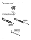
Insert operator cable through watertight connector nut.