9
STEP 6
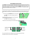
Limit Switch Adjustment
To Retract More
Turn Retract Limit
Screw Clockwise
To Retract Less
Turn Retract Limit
Screw Counter-
Clockwise
To Extend More
Turn Extend
Limit Screw
Counter-
Clockwise
To Extend Less
Turn Extend
Limit Screw
Clockwise
Remove limit switch end caps
Cycle the operator and adjust limits as
required. If the operator opens
automatically after closing, extend less
until gate remains closed.
Do not retract the extension tube too far
or the retract limit switch will not be
activated. (You can depress the LED
ENABLE button on the control board to
see when the actuator has reached it’s
limit)
1650 Adjustments
As you open and close the gates, you
will notice that the slave side moves 2-3
seconds slower than the master.
Tip: By welding stop tabs on the top
and bottom of the master side, the two
gates may now be adjusted so the slave
gate will close against the stop tabs of
the master gate and create enough
tension to prevent gates from moving
back and forth.
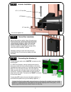
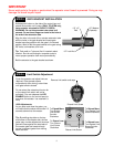
STEP 5 GATE BRACKET INSTALLATION
Activate push button on the side of the control box and
extend the actuator until it stops (PULL TO OPEN only,
leave actuator retracted for PUSH TO OPEN).
WARNING: Do not let extension tube rotate as it
extends. Do not insert fingers or tools in the hole at
the end of the extension tube
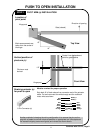
Align the hole in the end of the actuator extension tube
with the holes in the gate bracket and locate gate
bracket mounting position with the gate in the closed
position. Weld or bolt the gate bracket to the gate using
3/8” bolts, lock washers, and nuts.
Tip: Tack weld or C clamp at first if uncertain about
location. Run the unit through a complete cycle to
insure proper operation then mount permanently .
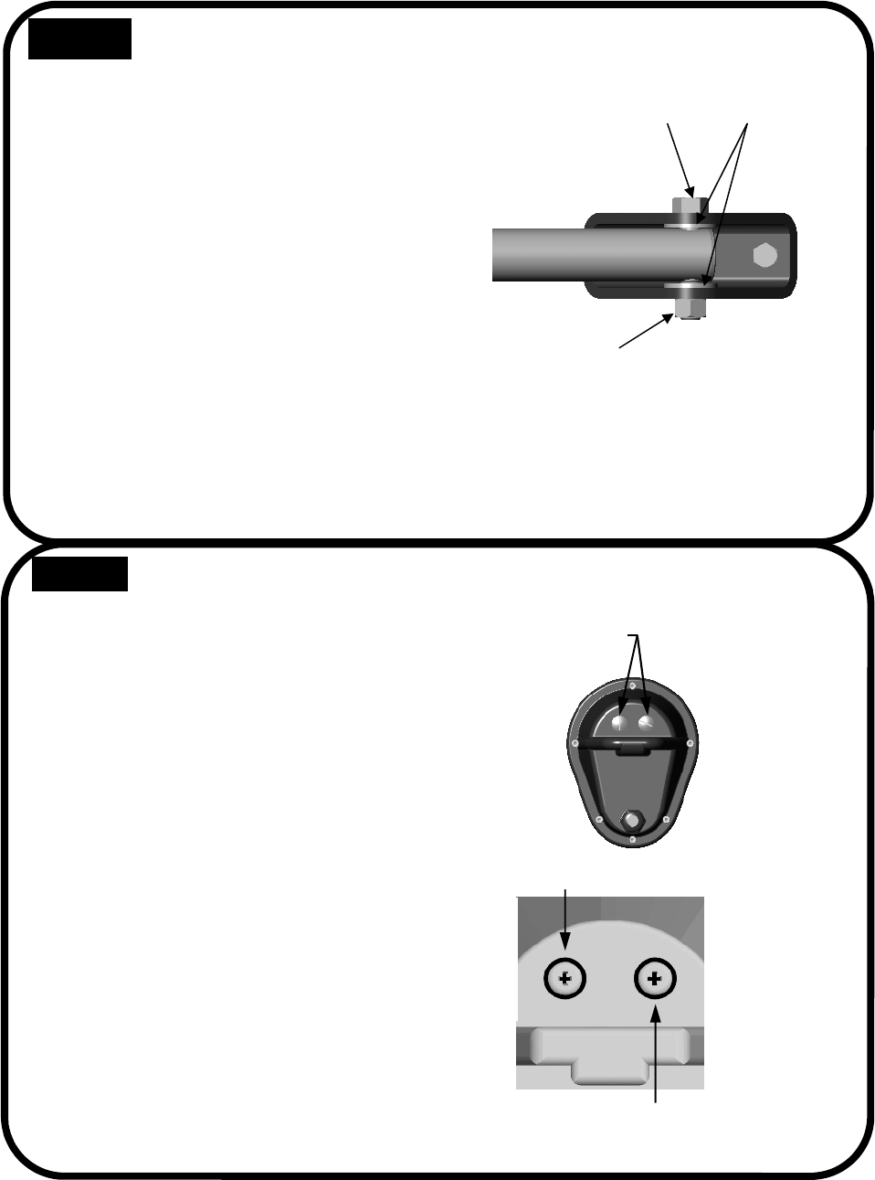
Bolt the actuator to the gate bracket as shown.
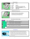
1/2” x 3”
Bolt
1/2” Lock Nut
1/2” Washer
(2 places)
Extend Limit Screw
Retract Limit Screw
IMPORTANT
Never weld parts to the gate or posts when the operator circuit board is powered. Doing so may
damage the board beyond repair.


