


14
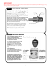
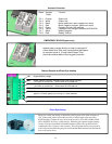
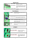
Board Actuator Function
Cable
Pin 1 Orange Open Limit
Pin 2 White Close Limit
Pin 3 Black Motor (positive on open, negative on close)
Pin 4 Red Motor (negative on open, positive on close)
Pin 5 Green Common for both limit switches
Pin 6 Yellow Feedback from intelligent actuator(816E/816EX)
Pin 7 Black Battery Negative
Pin 8 Red Battery Positive
1
3
5
7
2
4
6
8
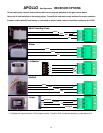
Actuator Connector
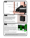
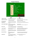
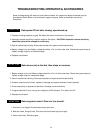
Applies battery voltage directly to motor to open gate if
control board fails. User must unplug before gate opens
to maximum travel or 15 amp fuse will open. Fuse
should be checked before returning gate to service.
EMERGENCY BYPASS (open only)
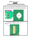
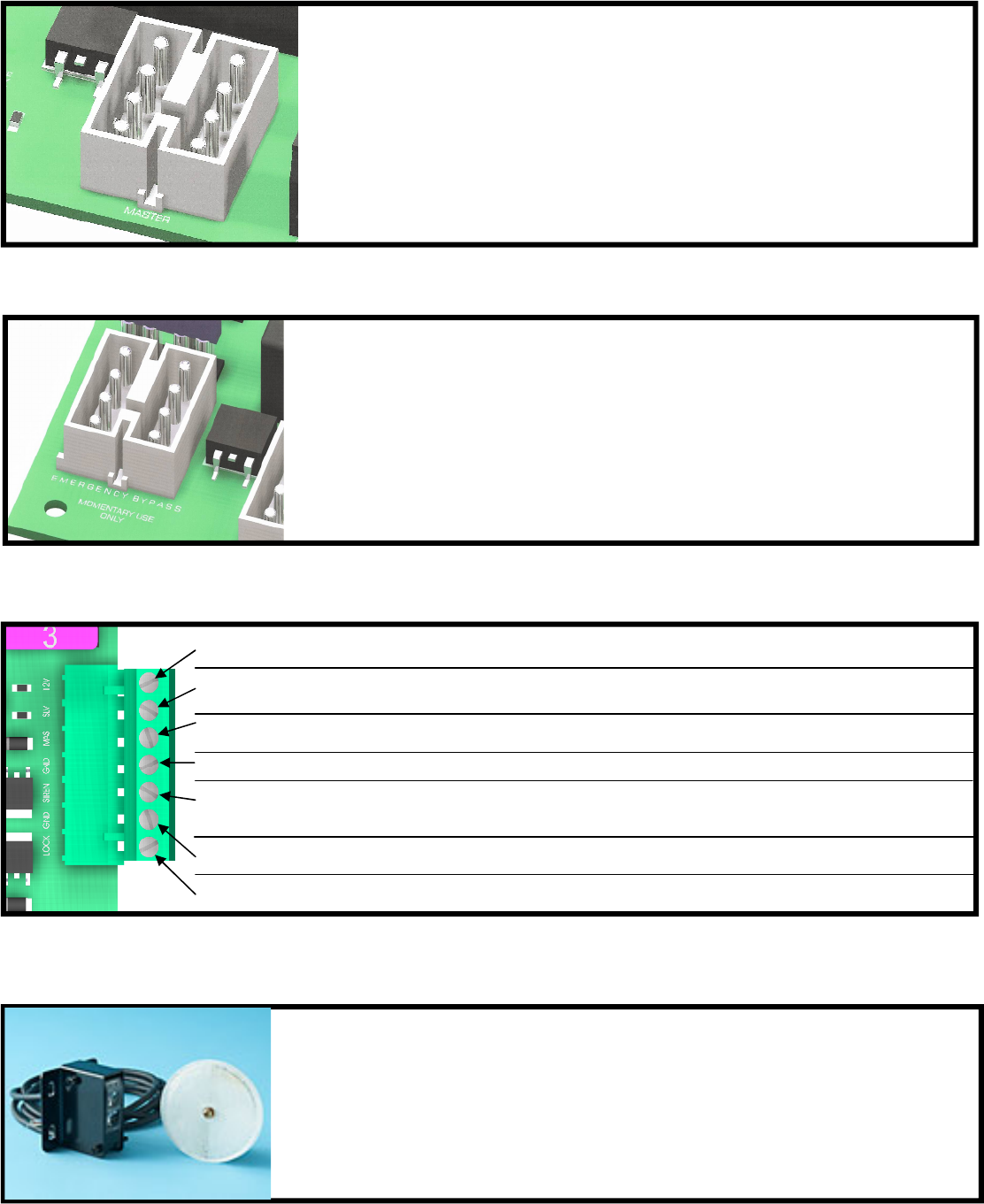
Photo eye / safety loop wiring. Connect the positive power wire of the accessory to
12V. Connect the ground wire of the accessory to MAS (upper right area of the
835/836 board). Connect the relay wires of the accessory as normal: COM to GND.
NO to SAFETY (#14) (for a safety device). When the gate operator begins opening
(comes off of the closed limits) the MAS terminal will become a ground and will
complete the flow of power to the accessory. This will power the accessory up and it
will work as normal until the gate gets closed and the MAS terminal switches and the
device will power down.
Photo Eye Hookup
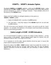
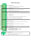
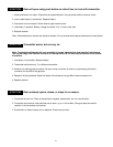
12V Supplied battery voltage
MAS Master Operator Indicator (indicates master side of gate is closed)
+12V when on closed limit. Ground when off of closed limit.
SLV Slave Operator Indicator (indicates slave side of gate is closed)
+12V when on closed limit. Ground when off of closed limit.
GND Battery supplied ground
SIREN Connect to siren +
applies +12V when gate(s) are running, or in hard shutdown
GND Battery supplied ground
LOCK Connect to lock + (optional) Magnetic or Solenoid type locks (Dip Switch #6 Selectable)
Remote Outputs and Photo Eye Hookup