Component
Module*
AC Power
~
~
Door Strike
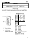
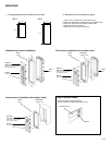
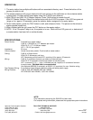
WIRING DIAGRAM:
Install jumper
between D+/D-
GW-LE8
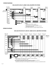
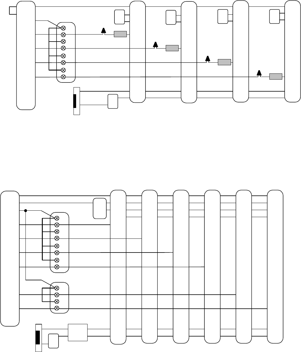
GW-LE8 WITH GW-4P, USING C-ML/A MASTER STATIONS
NOTES:
1. * Install bare wire end to "1" terminal
(DAK-2S contains two component modules).
2. Only components of the entrance panel that include wire
connections are shown here.
3. See C-ML/A instructions for complete installation information.
C-ML/A
-
+
SKK-620
E
-
+
1
L
L
C-ML/A
-
+
SKK-620
C-ML/A
-
+
SKK-620
GW-4P
1
2
3
4
Component
Module*
Component
Module*
Component
Module*
E
-
+
1
L
L
E
-
+
1
L
L
C-ML/A
-
+
SKK-620
E
-
+
1
L
L
D+
D-
Yel
Blu
Blu
Blu
Blu
Blu
Blu
Blu
Blu
RY-PA
~
~
AC Power
Door Strike
BlkYel
LEF-3L #1
GW-LE8
-
+
PS-12C
Remove E/-
jumper on all
masters.
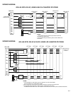
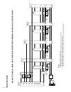
GW-LE8 WITH GW-4P & GW-2P, USING LEF-3L MASTER STATIONS
GW-4P
GW-2P
E
-
+
R
1
Brn
Wht
E
-
+
R
1
Brn
Wht
E
-
+
R
1
Brn
Wht
E
-
+
R
1
Brn
Wht
E
-
+
R
1
Brn
Wht
E
-
+
R
1
Brn
Wht
D+
D-
Yel
Blu
Blu
Blu
Blu
Blu
Blu
Blu
Blu
1
2
3
4
1
2
NOTES:
1. In this example, the door station rings in on station #1 of each master station.
It can be wired to any unused station number.
2. Only components of the entrance panel that include wire connections are shown here.
3. For complete wiring information, please see the LEF-3L instructions.
If additional master stations are to be installed in each office/suite, wire them per the standard instructions.
WIRING DIAGRAM:
LEF-3L #2 LEF-3L #3 LEF-3L #4 LEF-3L #5 LEF-3L #6
Pg. 2


