


7
Receiving And Handling
For future reference, record machine serial number
on front cover of this manual in the space provided.
The following instructions are presented in the order
recommended for setting up and installing the
case former, as well as for learning the operating
functions and adjustments. Following them step by
step will result in your understanding of the machine
and an installation in your production line that best
utilizes the many features built into the case former.
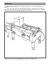
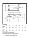
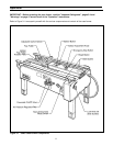
Refer to Figure 3-1 to identify the various
components of the case former.
After the machine has been uncrated, examine the
case former for damage that might have occurred
during transit. If damage is evident, file a damage
claim immediately with the transportation company
and also notify your 3M Representative.
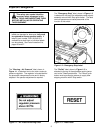
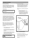
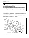
Figure 2-1 – Bed Height Adjustment
Installation and Set-Up
Machine Set-Up
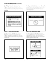
Important – Read "Warnings", on page 12,
before attempting to set up the case former
for operation.
Note – A tool kit consisting of metric open end
and hex socket wrenches is provided with the
machine. These tools should be adequate to set
up the machine, however, other tools supplied by
the customer will be required for machine
maintenance.
1. Follow "Unpacking Instructions" label attached
to corrugated packing cover.
Use appropriate material handling equipment to
remove the machine from the pallet and move it
into position.
Whenever the machine is lifted with a fork truck,
insure that the forks span completely across the
machine frame and do not contact any
mechanism under the machine frame.
Refer to Figure 2-1 and adjust the bed height as
follows:
(a) Block up the machine frame to allow
adequate leg adjustment.
(b) Loosen, but do not remove, two M8 x 16
mm socket screws in one leg. Adjust
the leg length for the desired bed height.
Retighten the two screws to secure the
leg. Adjust all four legs equally.
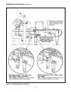
3. Install case former in production line.
Refer to Figure 2-2 for installation set up. Case
former bed must be level and equal or slightly
higher than case sealer bed height.
Install mounting brackets as shown in
Figure 2-2.
2. Adjust machine bed height.
The case former is equipped with four adjustable
legs that are located at the corners of the frame.
The legs can be adjusted to obtain different
conveyor bed heights from 610 mm [24.0 inch]
minimum to 775 mm [30.5 inch] maximum.
CAUTION – Machine weighs
approximately 85 kg ]190 lbs]
uncrated.