Altivar
®
58 TRX AC Drives
Drive Control Parameters
49
09/2003
© 2000–2003 Schneider Electric All Rights Reserved
DRIVE CONTROL PARAMETERS
Drive control parameters can be viewed and modified only when the access
locking switch on the keypad display is in the total unlock position (see page
24). They can be modified only when the motor is stopped.
Two-Wire Control
The drive controller is factory-configured for two-wire control. The two-wire
control function controls operation direction using maintained contacts.
Depending on whether one or two directions of operation are required by the
application, one or two logic inputs must be assigned to this function. An
example of wiring for two-wire control is shown to the left. Three operating
modes are possible:
• Detection of the state of logic inputs.
• Detection of a change in the state of logic inputs.
• Detection of the state of logic inputs with Forward operation having priority
over Reverse operation.
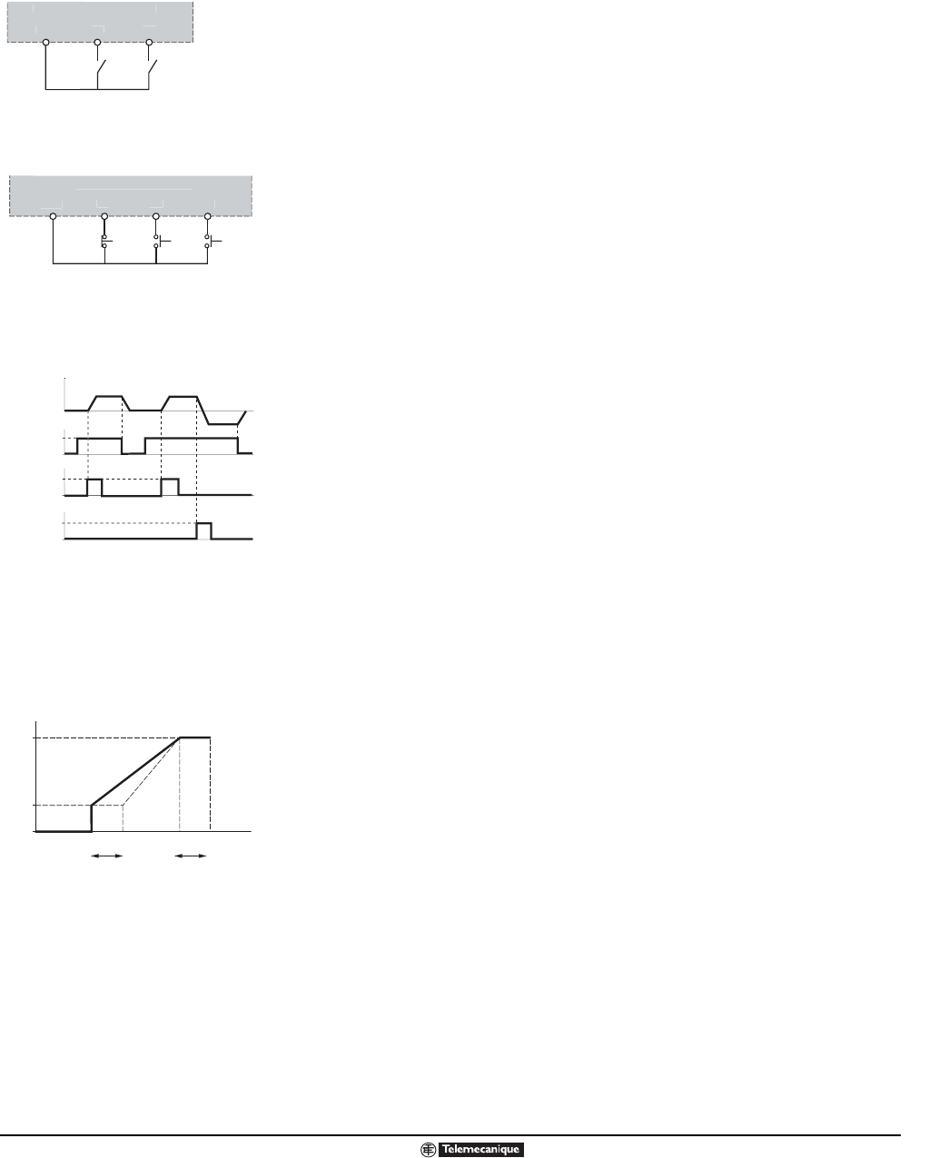
Three-Wire Control
The three-wire control function controls operation and stopping direction
using momentary contacts. Depending on whether one or two directions of
operation are required by the application, two or three logic inputs must be
assigned to this function. An example of wiring for three-wire control is shown
to the left. Three-wire control is appropriate for all types of applications with
one or two operating directions.
Reverse Inhibit
This function disables reverse operation. It disables the REV key on the
keypad display and also prohibits reverse operation commanded by the PI
Regulator or Speed Reference Summation functions. Applications such as
those involving pumps, fans, or other applications where reverse operation
may cause mechanical damage may require reverse to be disabled.
Analog Input Configuration
This parameter allows Analog Input 2 (AI2) on the drive controller to be
redefined to accept a range of signals. The input can be configured for 0 to
20 mA, 4 to 20 mA, or the minimum value (X) and maximum value (Y) can be
user assigned by programming X and Y (with 0.1 mA resolution). Reverse-
acting operation can also be configured. For example, 20 to 4 mA, where 20
mA equals low speed and 4mA equals high speed.
Keypad Command
When this parameter is set to Yes, the drive controller can be controlled by
the keypad. The factory default is No. Enabling this parameter allows
operation of the drive controller with the keypad RUN, STOP/RESET, and
FWD/REV keys. In this mode of operation, the speed reference is entered in
hertz or in customer defined units by using the keypad up or down arrow
keys. Also, a logic input configured for Freewheel Stop, Fast Stop, or Stop by
DC Injection will remain active at the control terminal strip.
Stop Priority
This parameter allows the keypad STOP key to remain active even if the drive
is being commanded via the terminal strip or a serial connection. The factory
default is Yes. If set to No, the keypad STOP key will not be active and the
drive controller will not stop when it is pressed.
ATV
ontrol Terminals
LI1 = Forward LIx = Reverse
2-wire.eps
Two Wire Control
LI
ATV
control terminal
LI1 = Stop LI2 = Forward LIx = Reverse
3-wire.eps
Three Wire Control
Sto
F
rw
r
R
v
r
PlusMinusSpd.eps
Three Wire Control Timing
Diagram
AI 2
(mA)
0
LSP
HSP
XY20
Frequency
AnalogInp.eps
Analog Input 2 Scaling


