- 26 -
12) INSTALL OPTIONAL TOP SUPPORT ASSEMBLY:
A) The top support assembly provides supplemental support at the upper end of the
ramp. When used, the top support assembly replaces the Ramp Handrail End
Brackets.
i) Attach top support brackets with two each 5/16” x 1½" bolts and two each
5/16” flat washers.
NOTE: There is a left and right top support bracket. The two 3/8” studs
aligned horizontally should be toward the end of the ramp (FIG. 39).
B) The following steps are done AFTER the ramp is resting on a supporting surface
and the top transition plate is installed. IMPORTANT: Read “INSTALLING A
SINGLE RAMP” and “ANCHOR TOP TRANSITION PLATE” sections and ensure
all steps are completed before proceeding with the steps that follow.
i) Install support tube bracket on each top ramp support bracket using two
each 3/8” nylock nuts into the threaded holes and two each 3/8” flat
washers. DO NOT TIGHTEN (FIG. 40).
ii) Install two each 3/8” x ½” hex bolts into the threaded holes on the support
tube bracket.
iii) Slide support tube into support tube bracket and onto base foot.
iv) Level support tube and then tighten 3/8” nylock nuts to secure support tube
bracket (FIG. 41).
v) Adjust height as needed, and then tighten bolts.
vi) Place end caps on support tube.
FIG. 39 FIG. 40 FIG. 41
- 7 -
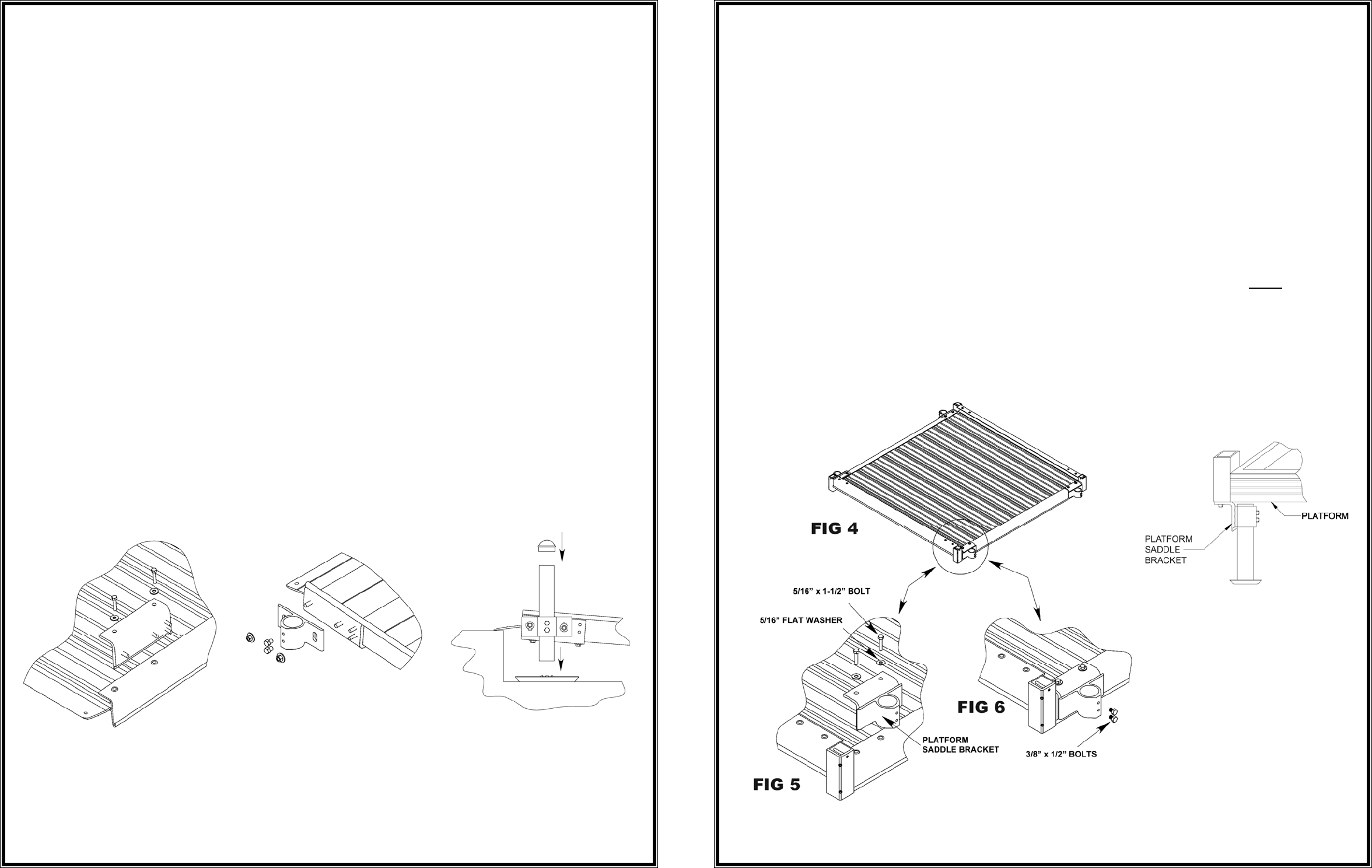
B) INSTALL SADDLE BRACKETS TO PLATFORM:
i) Place the surface of the platform face down, onto cardboard or a lawn so
that the platform is not damaged (scratched or dented).
ii) Each platform has two different configurations at each corner into which
the platform saddle brackets and support legs can be installed. To account
for obstacles, either position can be used as long as one platform saddle
bracket is installed in each corner.
iii) Position the platform saddle bracket over the threaded inserts located on
each outside corner of the platform (FIG. 4).
iv) Slide the platform saddle brackets into position (one end of the bracket will
slide into the groove). NOTE: If there are space limitations, the saddle
brackets can be installed under the platform as shown in FIG. 7 (if
necessary, support tubes can be cut to fit).
v) Using a ½” socket wrench, attach a platform saddle bracket to the platform
with two 5/16” x 1½” bolts and two 5/16” flat washers. DO NOT OVER
TIGHTEN
(FIG. 5). Repeat this step for all four platform saddle brackets.
NOTE: The 4 x 4, 5 x 4, and 5 x 5 platforms each use 4 (four) platform
saddle brackets.
vi) Once installed, start two each ⅜” x ½” bolts into the threaded holes in each
platform saddle bracket (FIG. 6) in order to secure the support tube.
FIG 7


