- 22 -
7) INSTALL LOOPS:
A) Install loops using same procedure as handrail with joiner assemblies.
8) INSTALL END CAPS:
A) Use end caps when there are any remaining open ends on the handrails.
i) Push them in by hand or by using a rubber mallet, then twist caps once
they are in place.
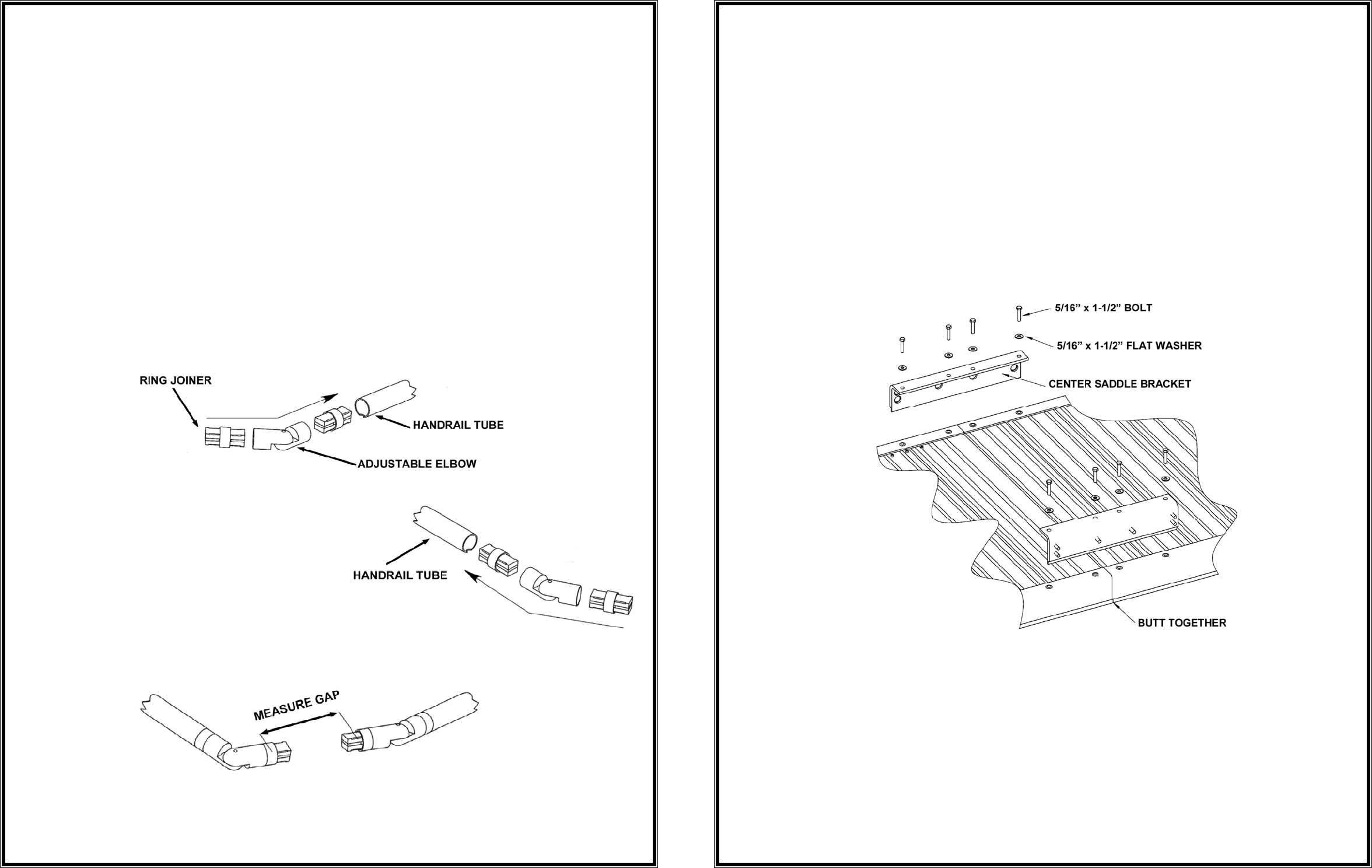
9) INSTALL OPTIONAL INSIDE CORNER HANDRAIL KIT:
A) Because each installation is unique, the components must be cut at the job site.
i) Slide a ring joiner into both ends of the adjustable elbow (FIG. 28).
ii) Slide a ring joiner/adjustable elbow assembly into each ramp handrail tube
(FIG. 29).
iii) Position both assemblies until they are aligned (FIG. 30).
iv) Measure the distance between the two ring portions of the ring
joiner/adjustable elbow assembly.
HELPFUL HINT: Use the supplied 5/32” and 3/16” allen wrenches to
lightly tighten the ring joiner/adjustable elbow assembly so they hold their
position while measuring.
FIG. 28
FIG. 29
FIG. 30
- 11 -
A) INSTALL RAMP SECTION(S):
i) Turn the ramp sections upside down on a flat surface (so that the ramps do
not get scratched or dented, it is recommended that this be done either on
the lawn or on a piece of cardboard).
NOTE: If you are installing a single ramp section, skip to 'INSTALLING A
SINGLE RAMP RUN’.
ii)
Butt the sections together end-to-end and ensure there is no gap.
iii) Position the two center saddle brackets over the threaded inserts found on
the end of each ramp section (FIG. 14).
iv) One edge of the center saddle bracket will slide into the groove of the ramp
section.
NOTE: Ramp sections are connected to create a ramp run using two
interchangeable center saddle brackets per joint. The center saddle
brackets are also where the handrails and support tube brackets are
attached, and are a part of the ramp support assembly. (FIG. 14).
FIG. 14
v) Attach the center saddle brackets using four each 5/16” x 1½” bolts and
washers per center saddle bracket.
vi) Tighten all eight bolts (four each per center saddle bracket).
NOTE: A maximum of three ramp sections may be joined in this manner.
vii) If necessary, install optional top support assembly at this time. See
'OPTIONAL TOP SUPPORT ASSEMBLY'.


