2-7
Preparing and Installing the 9A426-02 Module
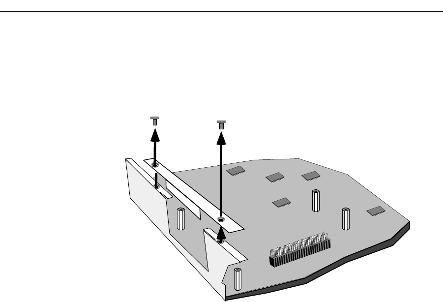
3. Use a Phillips-head screwdriver to remove the two flathead securing screws
(see Figure 2-5). Set the screws aside.
4. Remove the ATM-Port Retaining Plate. Set the plate aside.
Figure 2-5. Removing the ATM-Port Retaining Plate
Inserting an APIM into the 9A426-02 Module
1. Remove the module’s ATM-Port Retaining Plate.
2. Locate the area on the module where APIMs can be installed (shown in
Figure 2-4). This area contains eight standoffs (short metal posts). There are
four standoffs (arranged in an irregular rectangle) for each APIM (see insert in
Figure 2-4). There is a round-head screw at each end of these four standoffs.
3. Use a phillips head screwdriver to remove the four round-head screws from
the four standoffs. Set the screws aside.
4. Remove the APIM from its non-conductive bag.
5. Locate the APIM’s 80-pin (female) connector (see Figure 2-3).
6. Align the APIM’s female connector with the 80-pin male connector in the
APIM area of the 9A426-02 Module. Also align the APIM’s mounting holes
with the four standoffs in the APIM area of the module (see Figure 2-6).


