


Model 200EU-NOy Option Manual Addendum
22 05386 Rev. D
6.3 Checking Analyzer Flow Rate
The external sample pump is capable of maintaining the reaction cell pressure at less than 5.0
In-Hg-A. If a higher pressure is noted, the pump may need servicing. Check the pump and
pneumatic system for leaks or rebuild pump.
CAUTION!
Never operate the analyzer without the ozone destruct component properly seated and
connected within the pneumatic path. The ozone destruct is integrated into the converter
case, at the exhaust of the reaction cell, inside the instrument.
The sample flow as measured at ports “TO CONV/NO IN” and “FROM CONV/NOy IN” at the rear of
the analyzer should be 1000 100 cc/min.
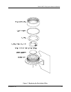
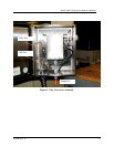
See Figure 1 for component locations.
6.4 Replacing the Converter
The heater, thermocouple, and converter assembly is designed to be replaced as a single unit.
Check Figure 3 for component location.
CAUTION!
The converter operates at 315C. Severe burns can result if not enough time is allowed for
the assembly to cool. Do not handle assembly until it is at room temperature.
1. Turn off the power to the bypass pump at the chassis front panel
2. Allow the converter to cool.
3. Disconnect the gas fittings and power cable from the can.
4. Remove the entire assembly from the chassis.
a. Remove the pneumatic fittings.
b. Remove the converter assembly from the chassis by loosening the 4 captive screws
that secures the assembly to the chassis.
5. Remove bottom bracket and re-attach it to the replacement converter assembly.
6. Install the assembly back into the analyzer.
7. Re-attach the electrical and pneumatic fittings. Leak check the assembly when
completed.
8. Turn the power back on. The insulation can emit a burnt odor for the first 24 hours;
this is normal. Allow the converter to burn-in for 24 hours, then re-calibrate the
instrument.